Multi-Axis Adjusting Apparatus

Inactive Publication Date: 2003-07-24
CORETRONIC
View PDF5 Cites 19 Cited by
  • Summary
  • Abstract
  • Description
  • Claims
  • Application Information

AI Technical Summary

Benefits of technology

0008] The objective of the present invention is to provide a multi-axis adjusting apparatus to adjust a light e

Problems solved by technology

In recent years, the dramatic development of electro-optical technologies has made data visualization a popular issue.
However, the bulk of the pile-structuredadjusting apparatus 20 is contradictory to

Method used


Image

  • Multi-Axis Adjusting Apparatus
  • Multi-Axis Adjusting Apparatus
  • Multi-Axis Adjusting Apparatus

Examples


Embodiment Construction

[0018] A preferred embodiment of the present invention will be explained with reference to the accompanying drawings.

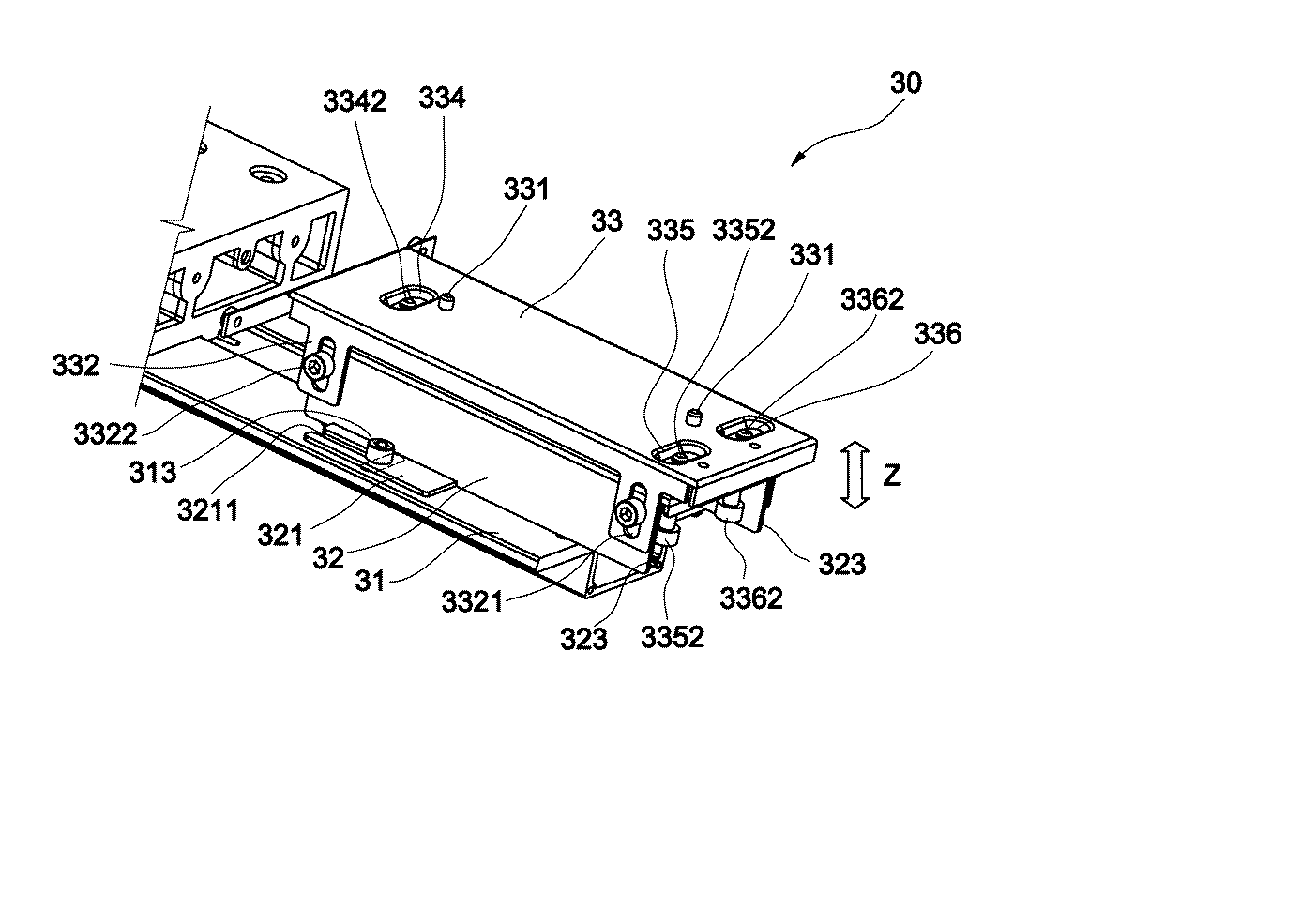
[0019] Please refer to Figs. 3 and 4, the adjusting apparatus 30,used in light engine, comprises a base 31, a sliding seat32 installed on a upper surface of the base 31, a carrier 33 installed on an upper surface of the sliding seat32, and at least one fixing pin331 installed on an upper surface of the carrier 33 for fixing and adjusting a light engine (not shown) Wherein, along a central line of the upper surface of the base 31 has the n-shaped sliding seat 32, relative positions of diagonals of two sides of the sliding seat 32 have protrusive sliding plates 321 and 322. The sliding plates 321 and 322 are close and smooth to the upper surface of the base 31, and two U-shaped slots 3211 and 3221 with reverse opening are along the central line of base 31. Corresponding to central locations of the U-shaped slots 3211 and 3221 and a direction of a central line perpendicu...


PUM


Abstract

Abstract of Disclosure The present invention is related to a multi-axis adjusting apparatus comprises a base with an upper surface, and each side of a central line of the base has at least one slot; a sliding seat, which is set on the upper surface of the base, and each of two ends of an upper surface of the sliding seat has at least one screw hole, each position of two sides of the upper surface of the sliding seat corresponding to the slot has at least one sliding plate, which has a U-shaped slot; a plurality of fixing screws, which are inserted into the U-shaped slot and the slot; a carrier, which is mounted on the upper surface of the sliding seat, and each of two ends of the upper surface corresponding to the screw hole has at least one fillister with one penetrating hole; plural adjusting screws are going through the screw holes and connecting to the penetrating holes by way of a floating structure. It is therefore the function of simultaneous adjustment of the multi-axis can be approached to rapidly complete the adjustment and reduce cost.

Description

Background of Invention[0001] Field of the Invention[0002] This invention is related to a projection system, especially an adjusting apparatus of a light engine in the projection system.[0003] Background of the Invention[0004] In recent years, the dramatic development of electro-optical technologies has made data visualization a popular issue. The demand and importance for a projection device capable of displaying data have impressed the electronics industry. Therefore, projection device manufacturers make an effort to provide a projection device that produces high image quality.[0005] Please refer to Fig.1, which is a schematic diagram of a rear projection television according to the prior art. The television comprises a housing 11, a base 12 installed inside the housing 11, an adjusting apparatus20 installed on an upward surface of the base 12, and a light engine 13 installed on an upward surface of the adjusting apparatus20 The light engine 13 emits light beams that contain image...

Claims


Application Information

Patent Timeline
IPC IPC(8): H04N5/655H04N5/74
CPCH04N9/3141H04N5/655
Inventor CHANG , FAN-CHIEHCHEN , KUO-WEN
Owner CORETRONIC
Why Eureka
Try Eureka