Backlight assembly and display apparatus having the same

a backlight assembly and display apparatus technology, applied in lighting and heating apparatus, instruments, optical elements, etc., can solve the problems of deteriorating display quality and damage to the optical member, and achieve the effect of preventing warpage and cleavage of the optical member caused by expansion or shrinkage, maintaining display quality, and preventing warpage and cleavage of the optical member

Active Publication Date: 2010-07-20
SAMSUNG DISPLAY CO LTD
View PDF10 Cites 7 Cited by
  • Summary
  • Abstract
  • Description
  • Claims
  • Application Information

AI Technical Summary

Benefits of technology

[0010]The present invention provides a backlight assembly preventing warpage and cleavage of an optical member.
[0014]The optical member in the embodiments disclosed herein is separated from the panel-guiding member. Therefore, warpage and cleavage of the optical member caused by expansion or shrinkage are prevented. Therefore, a display quality is maintained.
[0015]In an embodiment described herein, a backlight assembly for preventing warpage and cleavage of an optical member includes an optical member having at least one of a diffusion sheet, a prism sheet, and a brightness enhancing film, wherein the optical member is susceptible to expansion or shrinkage during temperature changes within the backlight assembly and a panel-guiding member for maintaining the optical member within the backlight assembly, wherein the panel-guiding member is spaced from the optical member by a distance that allows the optical member to expand within the backlight assembly without resulting in warpage or cleavage of the optical member.
[0016]A method for preventing warpage and cleavage within an optical member of a backlight assembly includes providing an optical member upon a light exiting face of a light guide plate, the optical member provided for enhancing optical properties of light exiting the light guide plate, providing a panel-guiding member within the backlight assembly for fixing the optical member within the backlight member, and, spacing the panel-guiding member from the optical member by a distance sufficient for allowing expansion of the optical member within the backlight assembly without causing warpage or cleavage of the optical member.

Problems solved by technology

When the optical member is heated, the optical member is expanded or shrunk resulting in damage to the optical member.
The optical member is, for example, warped which deteriorates display quality.

Method used


Image

  • Backlight assembly and display apparatus having the same
  • Backlight assembly and display apparatus having the same
  • Backlight assembly and display apparatus having the same

Examples


Embodiment Construction

[0024]Hereinafter, the embodiments of the present invention will be described in detail with reference to the accompanied drawings. In the drawings, the thickness of layers, films, and regions are exaggerated for clarity. It will be understood that when an element such as a layer, film, region, or substrate is referred to as being “on” another element, it can be directly on the other element or intervening elements may also be present.

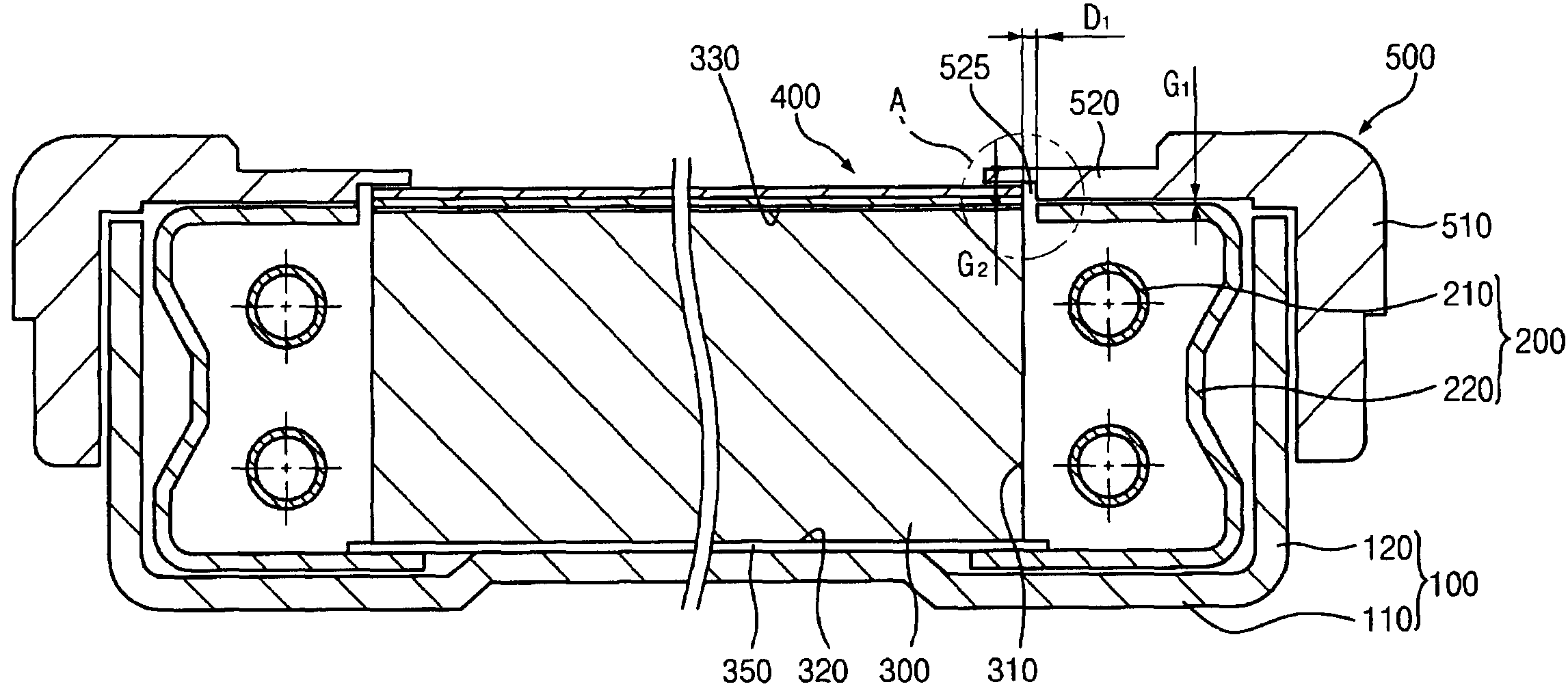
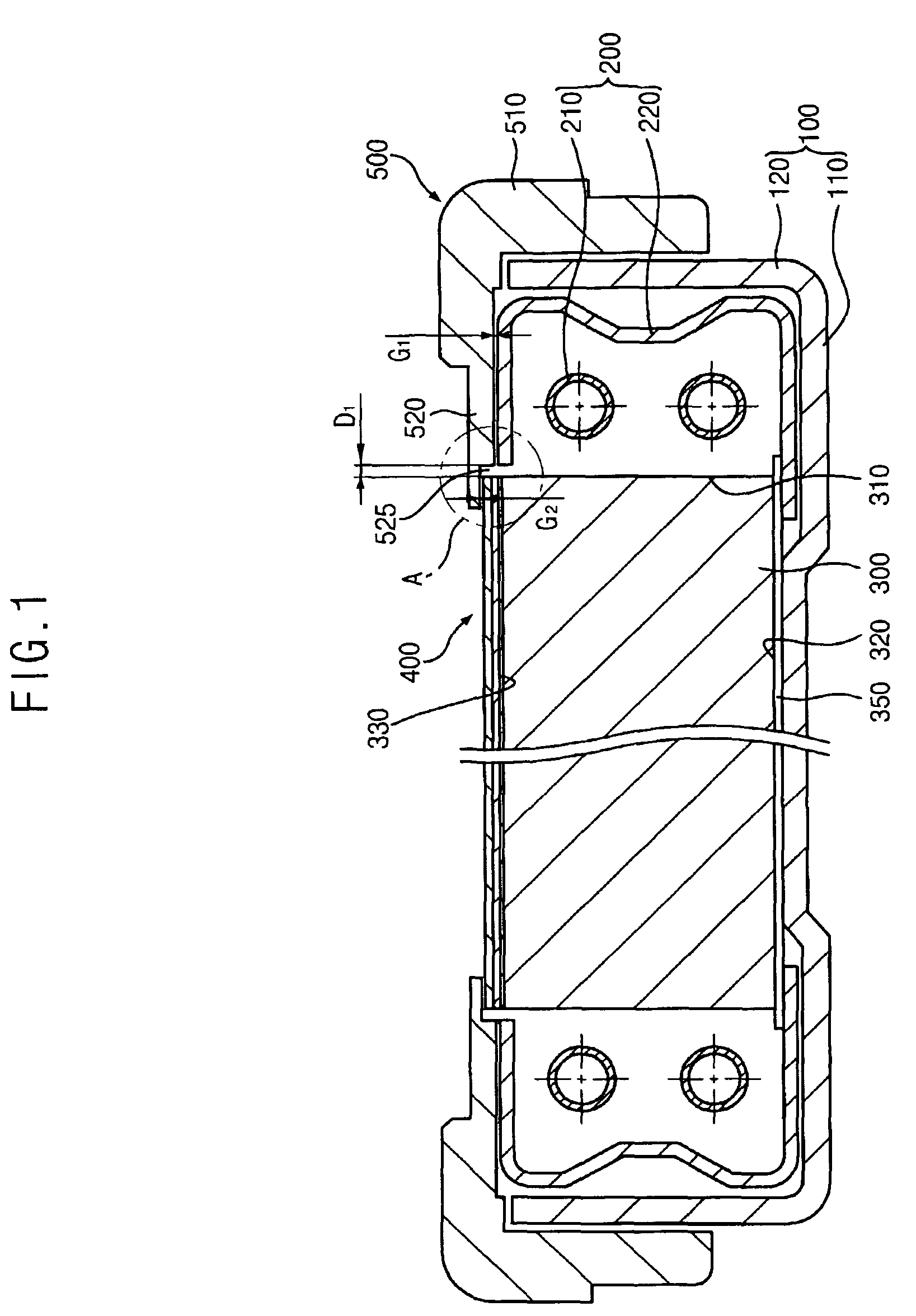
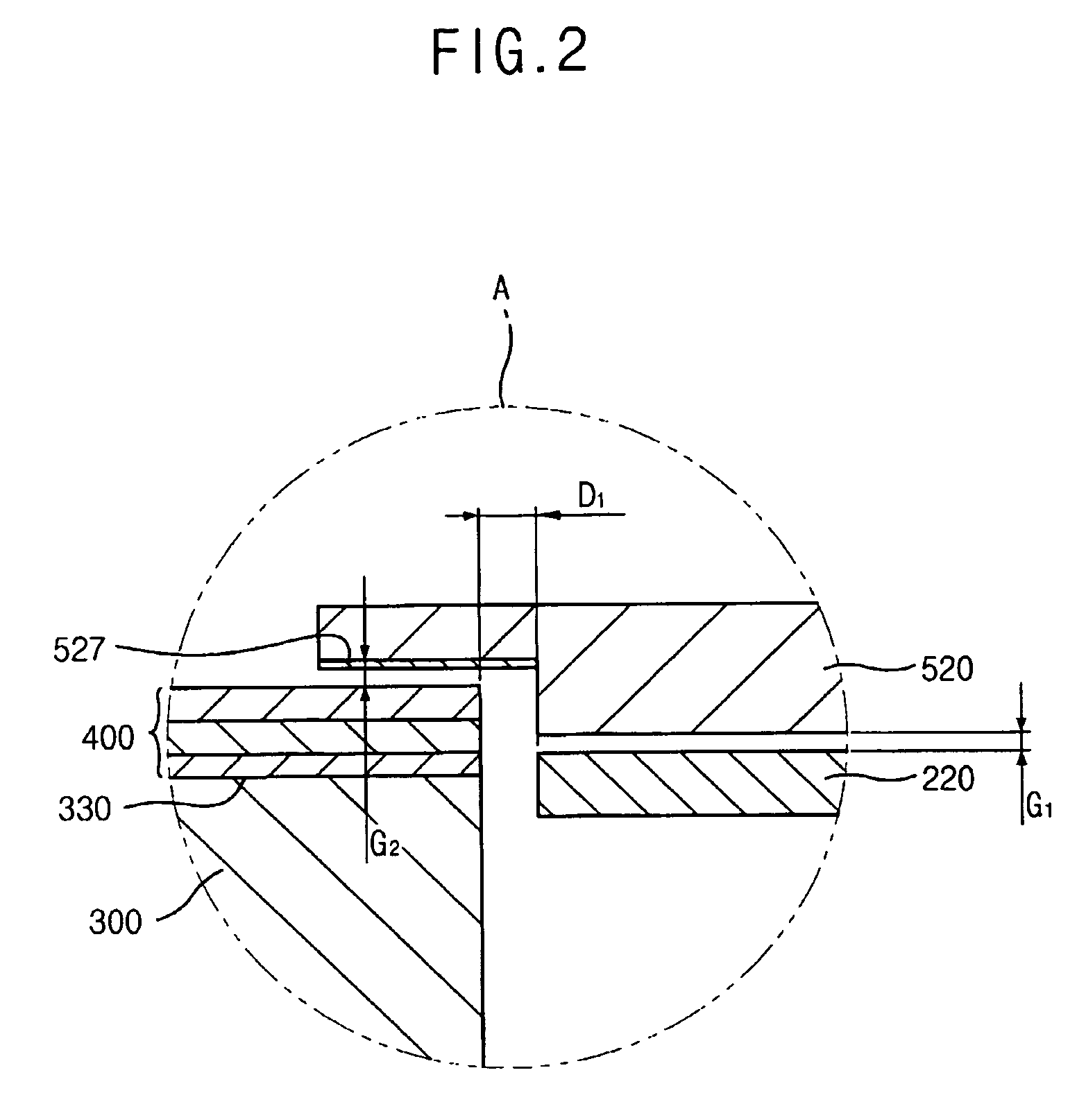
[0025]FIG. 1 is a cross-sectional view illustrating a backlight assembly according to an exemplary embodiment of the present invention, and FIG. 2 is an enlarged view illustrating portion ‘A’ in FIG. 1.

[0026]Referring to FIGS. 1 and 2, a backlight assembly according to one embodiment includes a receiving container 100, a light source unit 200, a light guide plate 300, an optical member 400 and a panel-guiding member 500.

[0027]The receiving container 100 includes a bottom plate 110 and a sidewall 120. The receiving container 100 may be made of, for exam...


PUM


Abstract

A backlight assembly includes a receiving container, a light guide plate, a light source unit, an optical member and a panel-guiding member. The receiving container includes a bottom plate and a sidewall extended from an edge portion of the bottom plate. The light source unit includes a light source generating light and disposed at side face of the light guide plate, and a light reflecting cover that covers the light source to reflect the light generated from the light source toward the side face. The optical member is disposed over the light guide plate. The panel-guiding member has a first plate combined with the sidewall of the receiving container, and a second plate extended from the first plate such that the second plate covers a portion of the optical member and is spaced apart from an upper face of the optical member. Therefore, warpage and cleavage of the optical member are prevented.

Description

CROSS-REFERENCE TO RELATED APPLICATIONS[0001]This application claims priority to Korean Patent Application No. 2004-62140 filed on Aug. 6, 2004 and all the benefits accruing therefrom under 35 U.S.C. §119, the contents of which are herein incorporated by reference in its entirety.BACKGROUND OF THE INVENTION[0002]1. Field of the Invention[0003]The present invention relates to a backlight assembly and a display apparatus having the backlight assembly. More particularly, the present invention relates to a backlight assembly preventing warpage of an optical member and a display apparatus having the backlight assembly.[0004]2. Description of the Related Art[0005]A display apparatus converts electric signals processed by an information processing apparatus into images. The display apparatus is characterized either into an active display apparatus that generates light or a passive display apparatus that uses external light to display the image.[0006]Examples of the active display apparatus...

Claims


Application Information

Patent Timeline
Patent Type & Authority Patents(United States)
IPC IPC(8): F21V7/04G09F13/04
CPCG02B6/0088G02F1/133308G02F1/133608G02F1/133615G02F2001/133317G02F2201/54G02F1/133317G02F1/1335
Inventor KANG, SANG-MINLEE, JEOUNG-GWENWON, YONG-GWANGKIM, TAE-HYUNG
Owner SAMSUNG DISPLAY CO LTD
Why Eureka
Try Eureka