A steel pipe cutting machine

A cutting machine and steel pipe technology, applied in the direction of pipe shearing device, shearing device, metal processing machinery parts, etc., can solve the problems of affecting cutting accuracy, increasing cutting cost, and low cutting efficiency, so as to improve cutting accuracy and increase jetting Range, the effect of improving the service life

Active Publication Date: 2016-03-09
QIDONG YONGXING RUBBER PROD
View PDF9 Cites 0 Cited by
  • Summary
  • Abstract
  • Description
  • Claims
  • Application Information

AI Technical Summary

Problems solved by technology

[0004] The clamping mechanism in the above patent only realizes the clamping of the steel pipe through the cooperation of the cylinder and the positioning block. This method is limited to clamping a single steel pipe. If multiple steel pipes need to be cut at one time, multiple steel pipes need to be clamped , and when the cylinder squeezes the side wall of the steel pipe, some steel pipes will tend to roll up and leave the cutting table, which will affect the cutting accuracy
Therefore, the above-mentioned steel pipe cutting machine can only cut a single steel pipe, and because the cutting tool will be worn after a period of time, it can only be overcome by changing a new cutting tool in the prior art, which not only causes waste of materials, but also reduces the cost of cutting. increase, frequent disassembly also leads to lower cutting efficiency

Method used


Image

  • A steel pipe cutting machine
  • A steel pipe cutting machine
  • A steel pipe cutting machine

Examples


Embodiment Construction

[0027] The following are specific embodiments of the present invention and in conjunction with the accompanying drawings, the technical solutions of the present invention are further described, but the present invention is not limited to these embodiments.

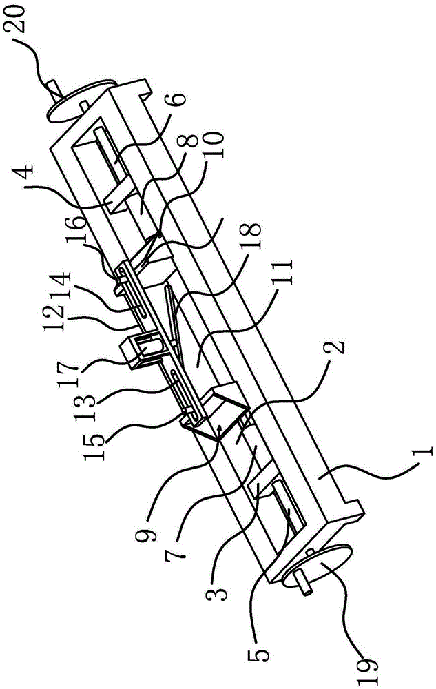
[0028] Such as figure 1 As shown, the steel pipe cutting machine includes a machine platform 34, and the machine platform 34 is provided with a clamping device for clamping the steel pipe 36 and a cutting device for cutting the steel pipe 36; the clamping device includes a clamping seat located on one side of the cutting device 1. The clamping seat 1 is fixed on the machine table 34. The length direction of the clamping seat 1 is perpendicular to the length direction of the machine table 34. The clamping seat 1 is provided with a chute 2 along its own length direction, and the chute 2 is slidingly set There are slider one 3 and slider two 4; the clamping device also includes a screw rod one 5 and a screw rod two 6 which ar...


PUM


Abstract

The invention belongs to the technical field of cutting and provides a steel pipe cutting machine which can improve the cutting efficiency of steel pipe cutting machines. The steel pipe cutting machine comprises a bench, and a clamping device, a cutting device, a trimming device, a cutting length adjusting device and a discharging device are disposed on the bench. The clamping device is used for clamping steel pipes, the cutting device is used for cutting the steel pipes, the trimming device is used for trimming a cutter, the cutting length adjusting device is used for adjusting the cutting length of the steel pipes, and the discharging device is used for moving the steel pipes into a containing box. When the steel pipe cutting machine is in use, the steel pipes are placed on the bench, the cutting length of the steel pipes can be adjusted through a measurement rod and a footstock, then the steel pipes are fixed by a first clamping block, a second clamping block and a pressure bar, the steel pipes cut by the cutter can be conveyed to the containing box through the discharging device, and when the cutter is abraded, a disc abrasive can be used for trimming the cutter. Cutting efficiency of the steel pipe cutting machine can be effectively improved.

Description

technical field [0001] The invention belongs to the technical field of cutting, and relates to a steel pipe cutting machine. Background technique [0002] There are many places on the car that require high mechanical strength for safety needs, such as anti-collision beams and other units, all use steel pipes. Before assembly, it is necessary to cut the steel pipe to a suitable length according to the needs of different models. [0003] my country's patent CN203140867U discloses a stainless steel pipe cutting machine, which solves technical problems such as unreasonable design of the prior art. It includes a working table, on which a clamping mechanism for clamping the stainless steel pipe and a steel pipe cutting mechanism for cutting the stainless steel pipe are arranged. The steel pipe cutting mechanism is arranged above the clamping mechanism and can drive it to rotate. Connected with the power mechanism, the steel pipe cutting machine also includes a transmission mecha...

Claims


Application Information

Patent Timeline
Patent Type & Authority Patents(China)
IPC IPC(8): B23D21/00B23D33/02B23D33/12B21D43/28B23Q11/10B24B3/36
Inventor 金海平
Owner QIDONG YONGXING RUBBER PROD
Why Eureka
Try Eureka