
Automatic Self-Centering Fixtures

A self-centering fixture and automatic technology, applied in the direction of clamping, positioning devices, manufacturing tools, etc., can solve the problems of clamping force, processing deformation, etc., and achieve the effects of small processing deformation, high positioning accuracy, and convenient loading and unloading

Inactive Publication Date: 2016-01-20
庄景惠
View PDF9 Cites 0 Cited by
  • Summary
  • Abstract
  • Description
  • Claims
  • Application Information

AI Technical Summary

Problems solved by technology

[0003] The present invention aims to solve the technical problems of control of clamping force and processing deformation in the clamping of thin-walled long parts, and provides an automatic self-centering clamp

Method used


Image

  • Automatic Self-Centering Fixtures
  • Automatic Self-Centering Fixtures

Examples


Embodiment Construction

[0009] The present invention will be further described below in conjunction with the accompanying drawings and embodiments.

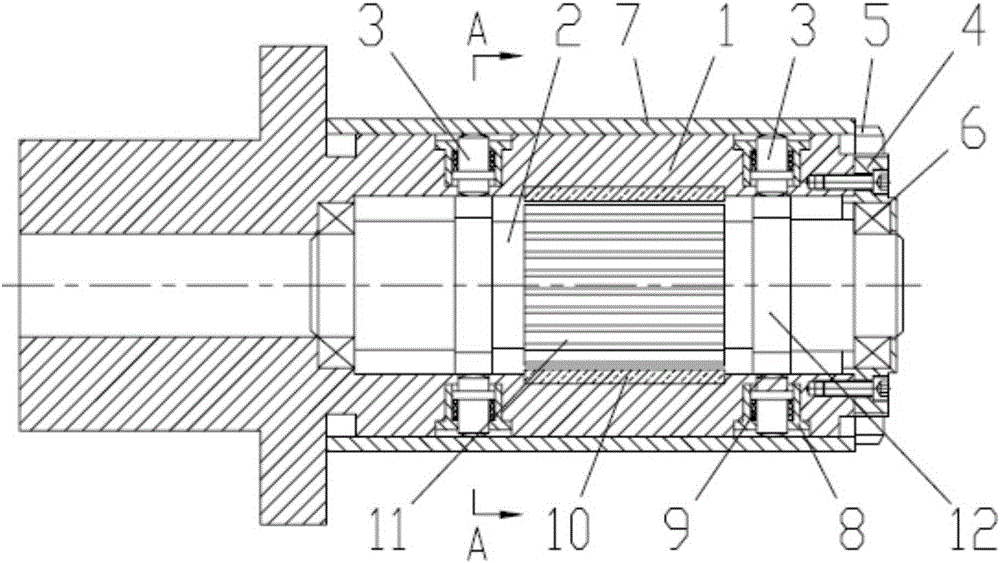
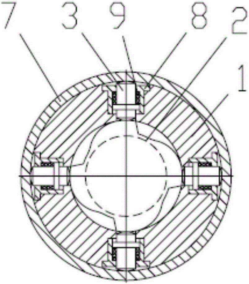
[0010] Such as figure 1 , as shown in 2, an automatic self-centering fixture, including mandrel 1, rotor shaft 2, positioning clamping column 3, end cover 4, end face compression nut 5, bearing 6, guide sleeve 8, return spring 9, motor Stator 10, motor rotor 11, outer cam column 12.

[0011] One end of the positioning column of the mandrel 1 is provided with a positioning step, the outer circle of the mandrel 1 is a positioning cylinder, a stepped inner hole is arranged in the positioning cylinder of the mandrel 1, and at least two A group of radial through holes, each group of radial through holes is evenly distributed with three or four radial through holes on the same cross section of the positioning column, the radial through holes are fixedly connected with a guide sleeve 8, and the guide sleeve 8 is movable Cooperate with the positioning clampin...


PUM


Abstract

The invention relates to an automatic self-centering clamp which comprises a mandrel, a rotor shaft, an end cover and guiding sleeves. One end of a positioning pillar of the mandrel is provided with a positioning step, and the outer circle of the mandrel is provided with a positioning pillar face. A step inner hole is formed in the positioning pillar face of the mandrel, and at least two sets of radial through holes are formed in the positioning pillar of the mandrel in the axial direction. Three or four radial through holes of each set of radial through holes are evenly formed in the same cross section of the positioning pillar, and the radial through holes are internally and fixedly connected with the guiding sleeves which are internally and movably matched and connected with positioning and clamping pillars. A motor stator is arranged in the middle of a step inner hole of the mandrel, and the two ends of the rotor shaft are connected with a connection hole in the front end of the step inner hole of the mandrel and an inner hole in the end cover fixed to the rear end face of the mandrel through bearings respectively. The two sides of the motor rotor of the rotor shaft are provided with outer cam pillars respectively, and each outer cam pillar is formed by evenly distributing three or four cams in the peripheral direction. The pillar face of each cam is in contact connection with the bottom end of the corresponding positioning and clamping pillar.

Description

technical field [0001] The invention relates to a centering fixture for thin-walled parts, in particular to an automatic self-centering fixture for thin-walled parts. Background technique [0002] In mechanical processing, some workpieces are positioned and clamped through their inner holes, but the existing fixtures either have complex structures, or are troublesome to unload, and most of them cannot achieve self-centering, and often cannot meet the conditions Requirements, resulting in poor machining accuracy. Therefore, the Chinese invention patent application number: 201110286659.4 discloses a self-centering fixture. The end of the blue plate has a section of external thread, and the section of external thread is equipped with an adjusting nut. A slidable retaining ring is sleeved on the outer circumference of the mandrel, and a pair of chutes are arranged on the mandrel. There is a pull rod in the center suspension, one end of the pull rod is fixed with the retaining ...

Claims


Application Information

Patent Timeline
Patent Type & Authority Patents(China)
IPC IPC(8): B23Q3/12
CPCB23B31/40
Inventor 张鸿来
Owner 庄景惠
Learn More