
Crane type multi-directional horizontal-movement multifunctional hydraulic lifting construction method

A technology of hydraulic lifting and construction method, applied in the direction of lifting device, etc., can solve the problems of increasing the difficulty of hoisting, difficulty in reaching the boom of a crane, and high hoisting height, and achieve the effect of preventing instability

Inactive Publication Date: 2014-04-30
CHINA NAT CHEM ENG THIRD CONSTR
View PDF5 Cites 13 Cited by
  • Summary
  • Abstract
  • Description
  • Claims
  • Application Information

AI Technical Summary

Problems solved by technology

The existing new equipment installation method is to hoist the equipment after the frame is completely completed, so that the manufacture of equipment and the construction of the frame can be carried out simultaneously, but the problem caused by this is that it is difficult for the boom of the crane to reach into the built Within frame buildings, cranes are therefore difficult to lift
For some equipment installed in the frame building, such as the hoisting of large urea synthesis towers and condensers, the weight of the equipment is large and the hoisting height is high. above the point, which increases the difficulty of hoisting
For the hoisting of this type of equipment, it is difficult to use the previous hoisting method

Method used


Image

  • Crane type multi-directional horizontal-movement multifunctional hydraulic lifting construction method
  • Crane type multi-directional horizontal-movement multifunctional hydraulic lifting construction method
  • Crane type multi-directional horizontal-movement multifunctional hydraulic lifting construction method

Examples


Embodiment Construction

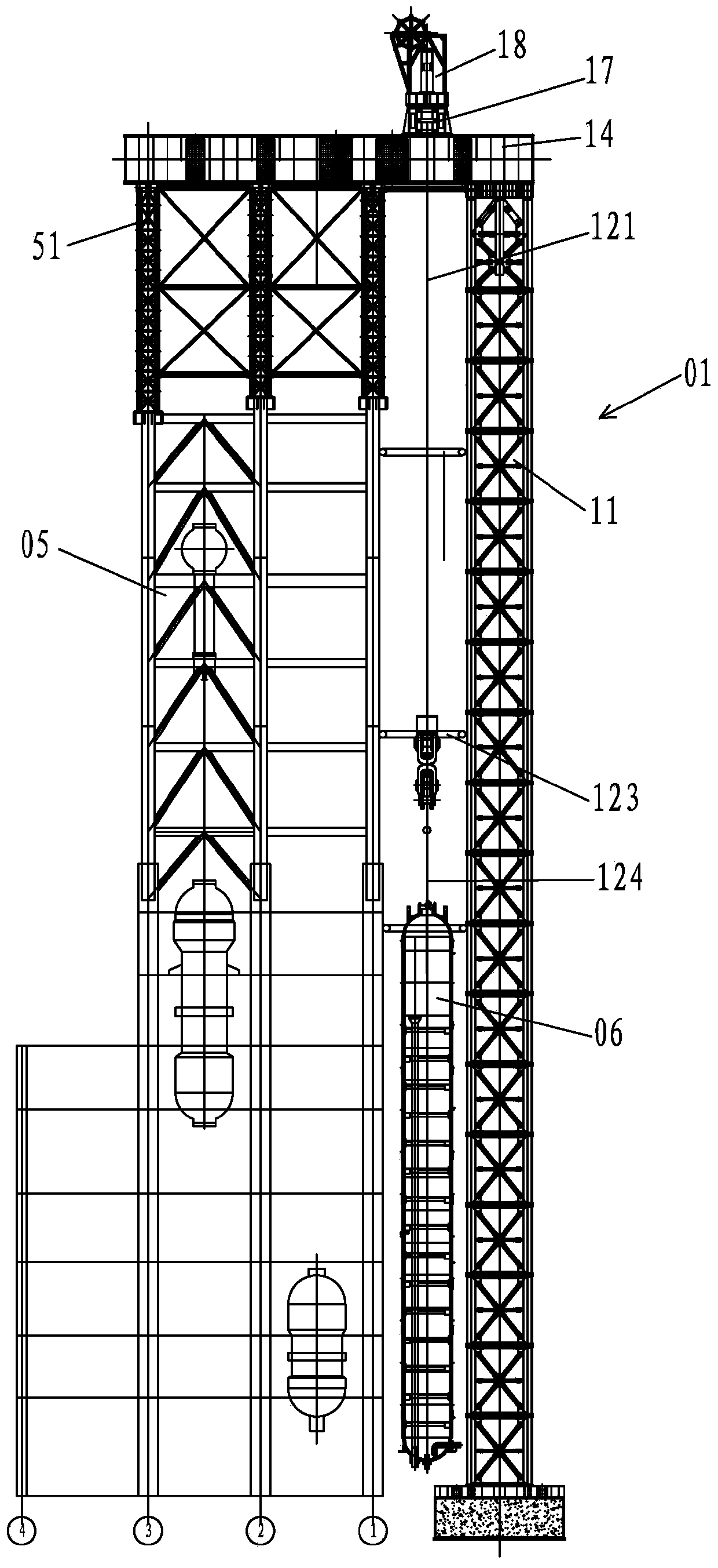
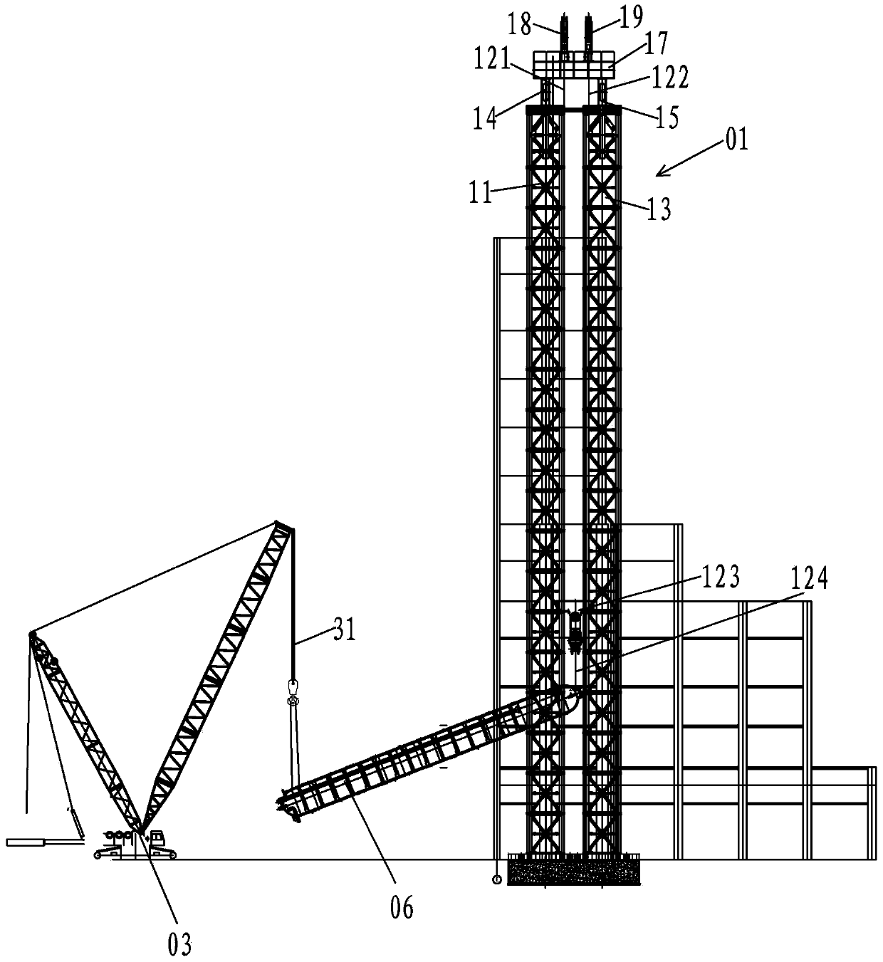
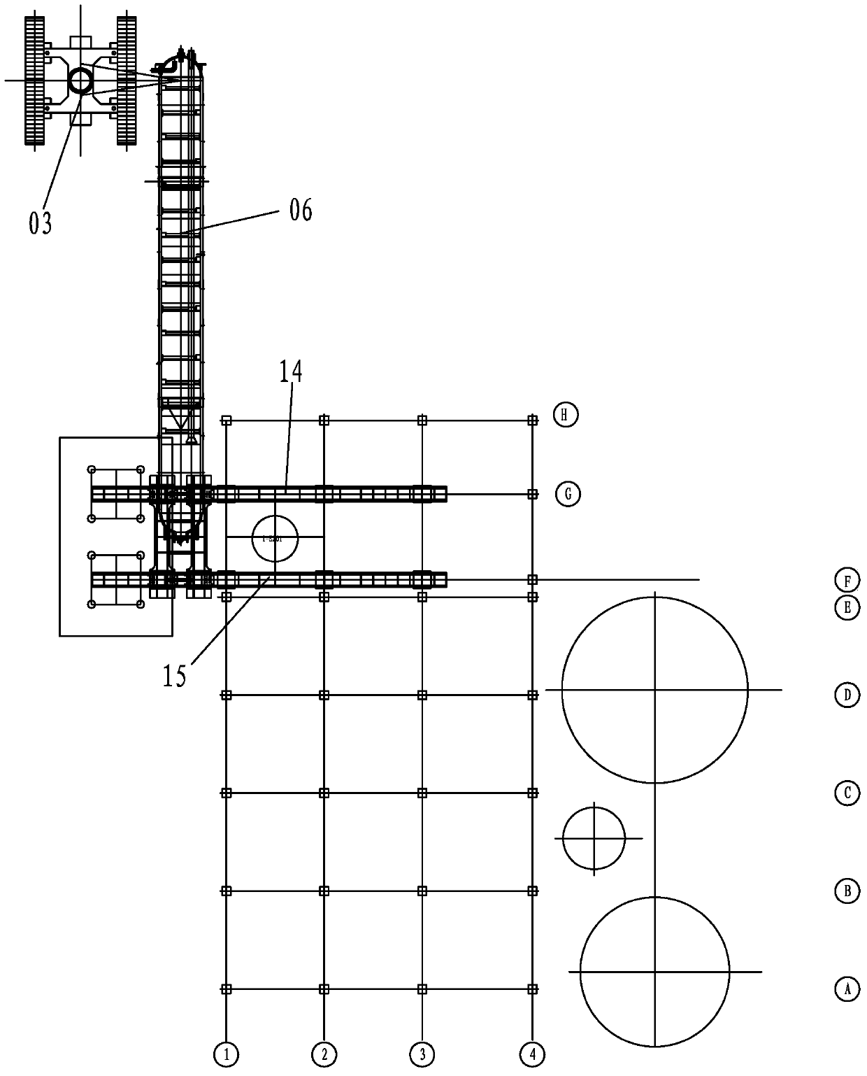
[0016] Such as figure 1 , 2 , 3, the gantry hydraulic lifting device 01 includes first and second gantry frames 11, 13, first and second load-bearing beams 14, 15, driving beam 17 and first and second hydraulic lifters 18, 19, The first and second hydraulic lifters 18, 19 are installed on the driving beam 17, the driving beam 17 is located above the first and second load-bearing beams 14, 15 and the two ends of the driving beam 17 are respectively supported on the first and second load-bearing beams 14 and 15, the driving beam 17 can slide on the first and second load-bearing beams 14 and 15, the first and second door frames 11 and 13 are vertically fixed on the ground, and the first and second load-bearing beams 14 and 15 are mutually Parallel, one end of the first load-bearing beam 14 is installed on the top of the first door frame 11, and the other end is installed on the temporary column 51 on the top of the frame building 05. One end of the second load-bearing beam 15 is...


PUM


Abstract

A crane type multi-directional horizontal-movement multifunctional hydraulic lifting construction method comprises the steps that (1) a gate-type hydraulic lifting device and a tail crane are installed outside a framework building, a main hoisting rope on a hydraulic lifter of the gate-type hydraulic lifting device is hung on a main hoisting lug of equipment to be hoisted in a tying mode, an auxiliary hoisting rope of the tail crane is hung on an auxiliary hoisting lug of the equipment to be hoisted in a tying mode, and the hydraulic lifter and the tail crane are loaded simultaneously until the equipment to be hoisted is in a vertical state; (2) the hydraulic lifter and the tail crane both stop being loaded, the auxiliary hoisting rope of the equipment to be hoisted is untied, the tail crane is removed, the main hoisting rope of the hydraulic lifter is loaded independently, and the equipment to be hoisted is lifted to a preset height; (3) the hydraulic lifter stops lifting, the hydraulic lifer is horizontally moved to the position above a position to be installed inside the framework building, the hydraulic lifer releases a steel strand to place the equipment to be hoisted to the preset position, and the main hoisting rope of the main hoisting lug is untied. By means of the crane type multi-directional horizontal-movement multifunctional hydraulic lifting construction method, the large equipment can be hoisted after the framework building is constructed.

Description

technical field [0001] The invention relates to the field of equipment hoisting, in particular to a driving-type multi-directional translation multifunctional hydraulic lifting construction method. Background technique [0002] In chemical construction projects, for the hoisting of large vertical equipment, the hoisting and moving method is usually used at present, which requires the use of multiple cranes, which are generally divided into main cranes and tail cranes. There is an auxiliary lifting lug at one end, the main lifting lug is set above the center of gravity of the equipment, and the auxiliary lifting lug is set below the center of the equipment. When hoisting, the main crane lifts the hook or rotates with the tail crane at the same time, and the tail crane moves forward or turns, so that the equipment gradually changes from a horizontal state to an upright state. After the equipment reaches the upright state, evacuate the tail crane and the main crane The crane b...

Claims


Application Information

Patent Timeline
IPC IPC(8): B66F11/00
Inventor 程志
Owner CHINA NAT CHEM ENG THIRD CONSTR
Learn More