A remote control valve

A technology for remote control of valves and valve bodies, applied to valve details, diaphragm valves, valve devices, etc., can solve the problems of easily dismantled actuators, inconvenient disassembly, and easy deformation of threads, so as to avoid the decline of sealing performance, facilitate installation and Ease of disassembly, installation and maintenance

Active Publication Date: 2016-05-18
CHONGQING WECAN PRECISION INSTR
View PDF7 Cites 0 Cited by
  • Summary
  • Abstract
  • Description
  • Claims
  • Application Information

AI Technical Summary

Problems solved by technology

[0002] The control valve generally controls the working process of the pressure device by controlling the direction and flow of the fluid. The existing control valve has a simple structure and poor internal sealing of the actuator. It is necessary to monitor its pressure and temperature in real time, and the existing control valves generally only have the function of controlling fluid on-off and flow rate, and the function is relatively single, which cannot meet the current needs. It is an integral fixed connection. When maintaining the control valve, it must be disassembled from the actuator in sequence. Not only is it easy to dismantle the actuator, but it also wastes a lot of manpower and time, which is very inconvenient; and the cables of the existing control valve are generally It is connected from the top of the actuator and then connected to the circuit board, which is not convenient for disassembly during installation and maintenance; the traditional detection method for closing and opening the valve is to use a contact switch or a travel switch, and the detection element used in this detection method The service life is short, and it needs to be replaced continuously during use, and then the executive body needs to be disassembled repeatedly, which is troublesome, and the airtightness inside the executive body cannot be guaranteed
[0003] In traditional control valves, the seal between the lower end of the valve stem and the inner wall of the valve stem is not good. When the fluid pressure is too high, the fluid will easily flow out through the gap between the valve stem and the inner wall of the valve stem, and flow into the upper part of the valve stem. Inconvenience or loss caused by the control mechanism or actuator; and the traditional control valve, the ball valve core, valve seat and stem are all installed in the main valve body, and the auxiliary valve body is connected to the inlet end of the main valve body through threads. After a long period of time or after the main and auxiliary valve bodies have been disassembled and assembled many times, the threads are easily deformed or broken, and the sealing between the two is difficult to guarantee, which may easily cause fluid leakage
[0004] The shortcomings of the existing technology are: the cables of the existing control valves are generally connected from the top of the actuator, and then connected to the circuit board, which is not convenient for disassembly during installation and maintenance; the traditional valve closing and opening in-position detection method The detection element used has a short service life and needs to be replaced regularly, which is very inconvenient and affects the sealing effect of the actuator; the seal between the lower end of the valve stem and the inner wall of the valve is not good, and the fluid is easy to flow into the actuator or control mechanism from the gap between the two , affect the valve work; at the same time, the sealing effect of the threaded connection between the main valve body and the auxiliary valve body is not very good, which is easy to cause leakage

Method used


Image

  • A remote control valve
  • A remote control valve
  • A remote control valve

Examples


Embodiment Construction

[0030] Below in conjunction with accompanying drawing and embodiment the present invention will be further described:

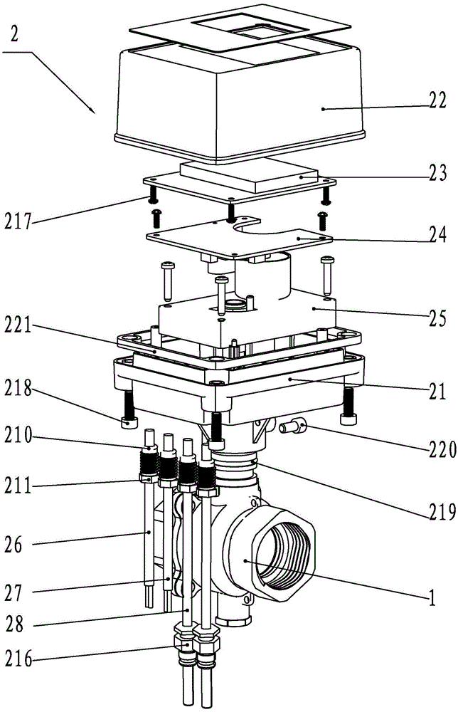
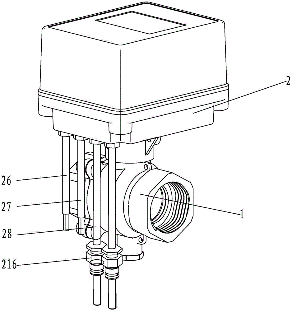
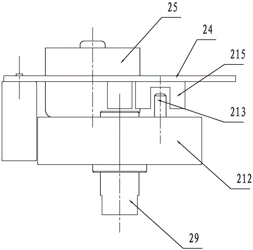
[0031] Such as Figure 1 to Figure 6 As shown, a remote control valve includes a valve body 1 and an actuator 2 installed on the valve body 1. The actuator 2 includes a base 21 and a valve cover 22 that is mounted on the upper end of the base 21. The base 21 and the valve cover 22 Connected by four hexagon socket countersunk head screws 218, a gasket 221 is installed at the connection between the base 21 and the valve cover 22, and a display circuit board 23 and a main circuit board 24 are sequentially installed between the valve cover 22 and the base 21 from top to bottom , deceleration motor 25 and connector 29, the upper part of the valve body 1 extends into the lower part of the base 21, and is detachably connected with the lower part of the base 21 through the hexagon socket head screw 220, and the display circuit board 23 is installed on the valve cover...


PUM


Abstract

The invention discloses a remote control valve which comprises a valve body and an execution body installed on the valve body. The execution body comprises a base and a valve cover with which the upper end of the base is covered. A display circuit board, a main circuit board, a gear motor and a connecting part are sequentially installed between the valve cover and the base from top to bottom. The upper portion of the valve body extends into the lower portion of the base, and is detachably connected with the lower portion of the base. The upper end of the connecting part is connected with the gear motor, and the lower end of the connecting part is connected with a valve rod of the valve body. A power source cable, an M-BUS cable and a temperature sensor cable extend into the execution body from the lower portion of the base, and are connected with the main circuit board. According to the remote control valve, the sealing effect is good, the valve body and the execution body can be conveniently assembled and disassembled, an in-place detection mechanism is more accurate in detection, the service life is long, liquid is effectively prevented from flowing out of the portion between the valve rod and the inner wall of a valve rod installation hole, it is ensured that an execution mechanism and a control mechanism are not disturbed, and assembly and disassembly of a main valve body and an auxiliary valve body are facilitated due to flange plate connection.

Description

technical field [0001] The invention belongs to the technical field of valve devices, and in particular relates to a remote control valve. Background technique [0002] The control valve generally controls the working process of the pressure device by controlling the direction and flow of the fluid. The existing control valve has a simple structure and poor internal sealing of the actuator. It is necessary to monitor its pressure and temperature in real time, and the existing control valves generally only have the function of controlling fluid on-off and flow rate, and the function is relatively single, which cannot meet the current needs. It is an integral fixed connection. When maintaining the control valve, it must be disassembled from the actuator in sequence. Not only is it easy to dismantle the actuator, but it also wastes a lot of manpower and time, which is very inconvenient; and the cables of the existing control valve are generally It is connected from the top of ...

Claims


Application Information

Patent Timeline
Patent Type & Authority Patents(China)
IPC IPC(8): F16K31/04F16K5/06F16K7/06F16K41/06
CPCF16K5/0631F16K5/0652F16K5/0694F16K31/042F16K31/046
Inventor 徐尚通
Owner CHONGQING WECAN PRECISION INSTR
Why Eureka
Try Eureka