Rotating drying cylinder

A technology of drying cylinder and outer cylinder, applied in drying, drying machine, drying solid materials, etc., can solve problems such as affecting the normal transportation of materials, decomposing toxic gas of sticky blocks, etc., to prevent continued deposition, prevent adhesion, structure simple effect

Inactive Publication Date: 2014-04-30
重庆信奇建材机械制造有限公司
View PDF0 Cites 7 Cited by
  • Summary
  • Abstract
  • Description
  • Claims
  • Application Information

AI Technical Summary

Problems solved by technology

[0003] The disadvantage of the existing rotary drying drum is that the material is easy to stick to the inner wall of the drying drum, and if the sticky block is too large, it will affect the normal transportation of the material, and the sticky block will decompose and produce poisonous gas when heated for a long time

Method used


Image

  • Rotating drying cylinder
  • Rotating drying cylinder

Examples


Embodiment 1

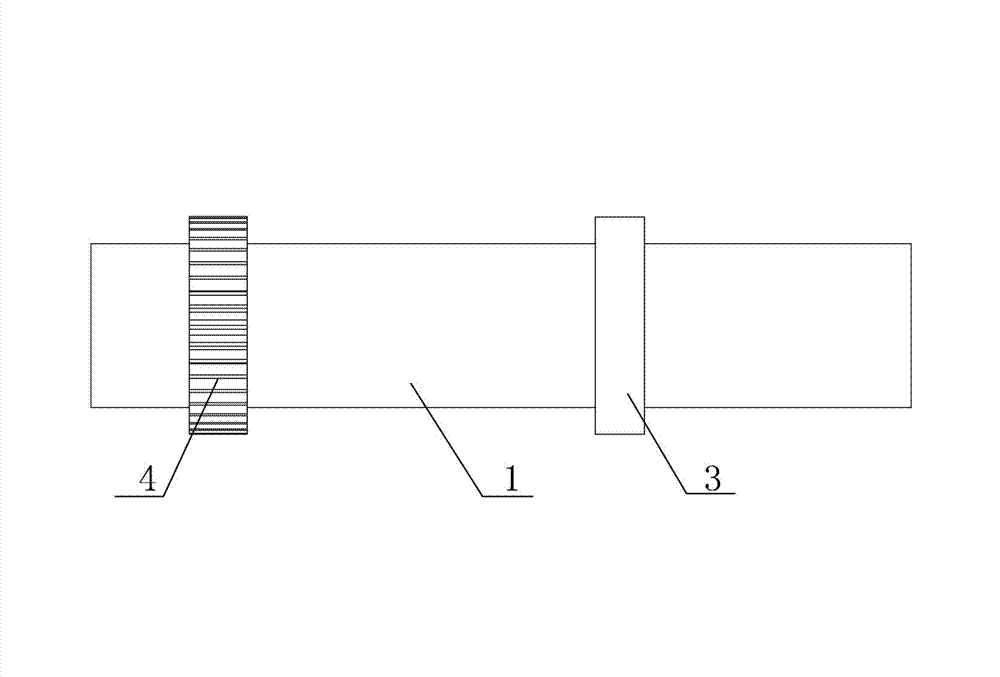
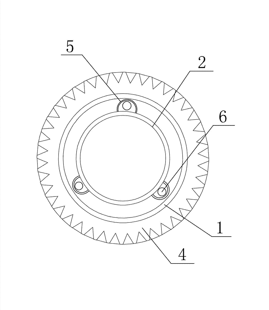
[0012] Embodiment 1: refer to figure 1 , figure 2 , a rotary drying cylinder, including an outer cylinder 1 arranged obliquely, an inner cylinder 2 built in the outer cylinder 1, a heating channel is formed between the inner cylinder 2 and the outer cylinder 1, and a roller is fixed on the outer circle of the outer cylinder 1 ring 3 and ring gear 4. The rotary drying cylinder is arranged on a supporting frame, on which a rolling ring seat and a ring gear seat are installed, the rolling ring seat meshes with the rolling ring 3 , and the ring gear seat meshes with the ring gear 4 . When the drying cylinder is in use, it is placed obliquely. The higher end of the outer cylinder 1 of the drying cylinder is the feed end, the lower end is the discharge end, and the higher end of the outer cylinder 1 is connected to the heater.

[0013] The outer wall of the inner cylinder 2 is fixed with a raised strip vibrating belt 5 along the axis, such as figure 2 There are three vibrating ...

Embodiment 2

[0014] Embodiment 2: The difference from Embodiment 1 is that a raised spiral vibrating belt is fixed along the axis on the outer wall of the inner cylinder.


PUM


Abstract

The invention belongs to drying equipment for removing liquids from solid materials or products and discloses a rotating drying cylinder. The rotating drying cylinder comprises an outer cylinder and an inner cylinder, the inner cylinder is built in the outer cylinder, a heating channel is formed between the outer cylinder and the inner cylinder, the outer cylinder is connected with a combustor, rolling rings and teeth rings are fixed on an outer circle of the outer cylinder, protruded vibrating bands are arranged on the outer wall of the inner cylinder along an axial direction, inner cavities are mounted on the vibrating bands, and steel balls are placed at positions of the inner cavities. The rotating drying cylinder has the advantages that the structure is simple, material bonding can be effectively prevented, and normal conveying of materials can be guaranteed.

Description

technical field [0001] This invention pertains to drying equipment for the removal of liquids from solid materials or articles. Background technique [0002] The drying of wet materials usually adopts a rotary drying cylinder. This drying cylinder is divided into an outer cylinder and an inner cylinder. The inner cylinder is equipped with a burner, and there is a heating channel between the outer cylinder and the inner cylinder. The angle between the drying drum and the horizontal plane is α=5°~10°. The feeding end is higher than the discharging end. There are two rolling rings fixedly connected to the outer circle. There is a gear ring between the rolling rings and a The supporting wheel is supported, and a ring gear seat is arranged under the ring gear. Driven by the power mechanism, the ring gear makes the drying cylinder rotate around the central axis. When the drying cylinder rotates, the materials in the inner cylinder are brought to a high place and then fall. Becaus...

Claims


Application Information

Patent Timeline
Patent Type & Authority Applications(China)
IPC IPC(8): F26B17/34F26B25/04
Inventor 张信聪
Owner 重庆信奇建材机械制造有限公司
Why Eureka
Try Eureka