Device and method for measuring engine valve landing radial deflection

A technology of engine valves and valves, which is applied in the direction of measuring devices, electrical devices, instruments, etc., can solve problems such as the analysis and research of unfavorable valve radial offset, and achieve the effects of simple structure, improved efficiency, and convenient long-term use

Active Publication Date: 2014-04-30
HANGZHOU DIANZI UNIV
View PDF4 Cites 12 Cited by
  • Summary
  • Abstract
  • Description
  • Claims
  • Application Information

AI Technical Summary

Problems solved by technology

[0003] At present, in the experiment of measuring the radial deviation of the engine valve seat, there is no unified experimental platform that is relatively conven

Method used


Image

  • Device and method for measuring engine valve landing radial deflection
  • Device and method for measuring engine valve landing radial deflection
  • Device and method for measuring engine valve landing radial deflection

Examples


Embodiment Construction

[0019] The present invention will be further described below in conjunction with the accompanying drawings.

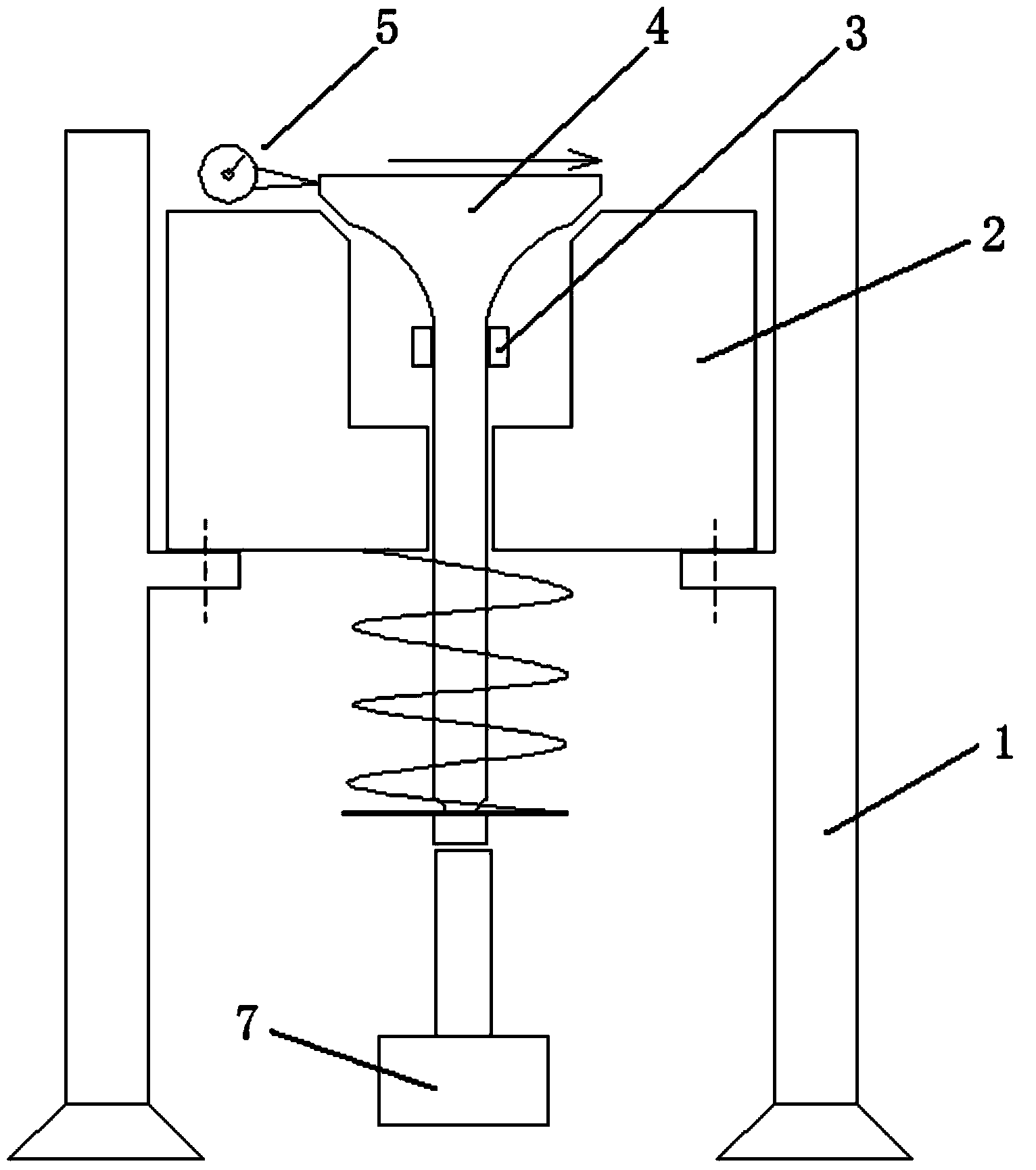
[0020] Such as figure 1 As shown, the engine valve seat radial offset calibration test bench includes: a bench 1, a cylinder head 2, a strain gauge 3, a valve 4, a dial indicator 5 and a screw lifter 7.

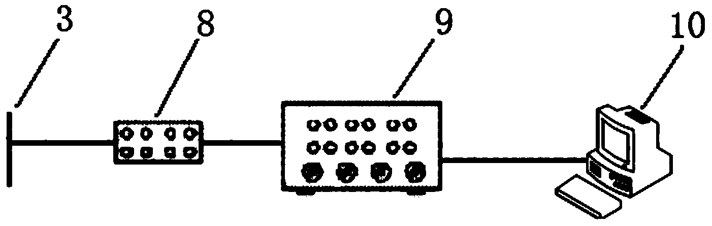
[0021] First paste the strain gauge 3 on the neck of the valve 4 to connect the bridge box 8, the strain gauge 9 and the host computer 10; assemble the valve 4 and the valve spring to the cylinder head 2; then fix the cylinder head 2 on the stand 1 , Use the lead screw lifter 7 to give it a lift against the end of the valve 4; finally put the dial indicator 5 against the side end of the valve 4.

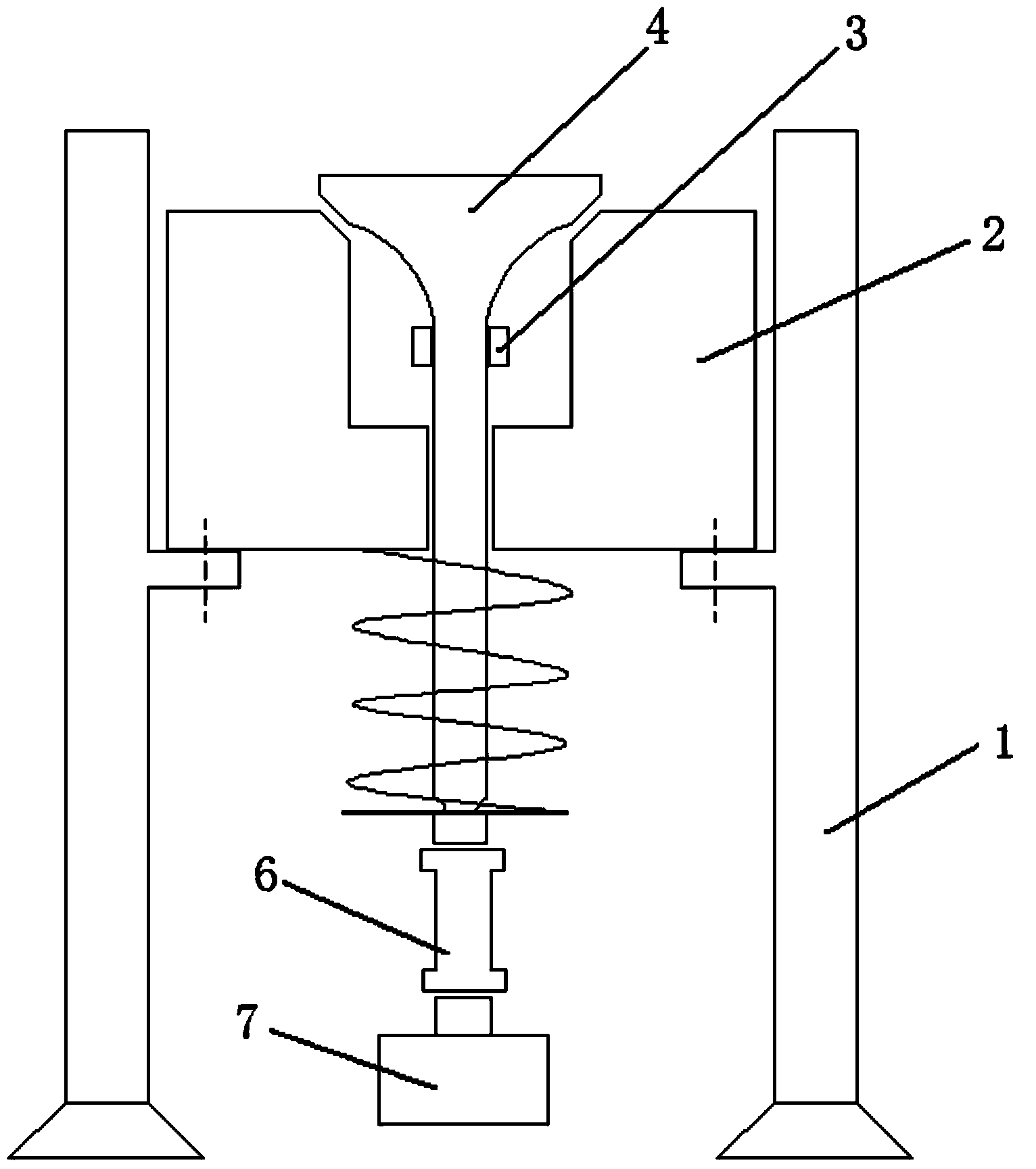
[0022] Such as figure 2 As shown in the test bench for the free seat of the engine valve, the valve 4 is first lifted up by a lift with the iron rod 6 and the lead screw lift 7, and then the iron rod is removed to allow the valve to sit freely, and the voltage change on t...


PUM


Abstract

The invention discloses a device and method for measuring engine valve landing radial deflection. The engine valve landing radial deflection is measured, static calibration is carried out firstly, and then landing of a valve is simulated to calculate the radial deflection of the valve. When a calibration test is carried out, strain foil is pasted on the neck of the valve, and a bridge box, a strain gage and an upper computer are connected. The valve and a valve spring are assembled on an air cylinder cover. Then, the air cylinder cover is fixed to a rack, and a lead screw lift abuts against the tail end of the valve to provide a stroke for the valve. Finally, a dial indicator abuts against the side end of the valve. Only the simple test device is needed, radial stress is exerted to the engine valve, the relation curve of voltages and the deflection is worked out according to data analysis, the voltage value of the strain foil is obtained at last through the valve free landing test, therefore, the deflection of the landing of the valve is calculated, the valve landing radial deflection is calculated, and test requirements are met.

Description

technical field [0001] The invention belongs to the technical field of engine detection, and relates to a device and method for measuring radial offset of an engine valve seat. Background technique [0002] The engine valve is an important part of the engine valve mechanism. It opens and closes regularly to ensure that the engine regularly inhales fresh combustible mixture for the cylinder during operation, and discharges the burned exhaust gas out of the cylinder in time. Whether it is reliable directly affects the performance of the engine. performance. Especially with the development of engine technology, the pressure in the cylinder increases, the speed increases, and the seating speed of the valve is often very high. However, since there is a gap between the valve and the cylinder head, the valve will deviate radially when it is seated, which will cause the valve to be eccentric when it is seated, and produce a great impact on the valve. As a result, the problems ...

Claims


Application Information

Patent Timeline
IPC IPC(8): G01B7/02
Inventor 刘忠民唐龙鑫余旭康吴军傅瑜杭
Owner HANGZHOU DIANZI UNIV
Why Eureka
Try Eureka