Method for detecting contact net geometrical parameters based on infrared image processing

A technology of infrared image processing and geometric parameters, which is applied in the direction of measuring devices, instruments, and optical devices, can solve the problems of poor anti-interference, low precision, and high cost, and achieve strong anti-sunlight interference and cost reduction.

Active Publication Date: 2014-04-30
CHENGDU NAT RAILWAYS ELECTRICAL EQUIP
View PDF8 Cites 28 Cited by
  • Summary
  • Abstract
  • Description
  • Claims
  • Application Information

AI Technical Summary

Problems solved by technology

[0007] The invention provides a method based on infrared image processing to realize the detection of catenary geometric parameters, whic

Method used


Image

  • Method for detecting contact net geometrical parameters based on infrared image processing
  • Method for detecting contact net geometrical parameters based on infrared image processing
  • Method for detecting contact net geometrical parameters based on infrared image processing

Examples


Embodiment 1

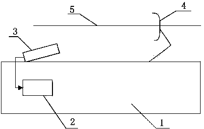
[0063] Such as figure 1As shown, a method for detecting geometric parameters of catenary based on infrared image processing described in this embodiment includes the following steps:

[0064] (a) if figure 1 As shown in the figure, 1 is the locomotive body, 2 is the processing host, 3 is the thermal imaging camera, 4 is the pantograph, and 5 is the contact wire. The thermal imaging camera is installed on the roof of the running locomotive and connected The pantograph is facing directly, and the thermal imaging camera is connected to the processing host for infrared image processing and storage. In this embodiment, the thermal imaging camera is installed at a position about 6 meters away from the position of the pantograph, and the shooting direction of the thermal imaging camera is the same as The angle between the horizontal plane is about 15°, at this time, the pantograph can completely appear in the field of view of the infrared thermal imaging camera, and the image effect...

Embodiment 2

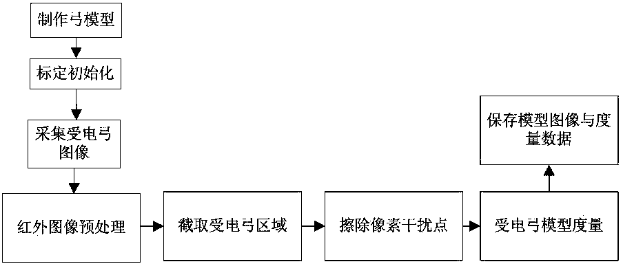
[0070] Such as figure 2 As shown, this embodiment optimizes and limits step (b) on the basis of embodiment 1, and the specific process of step (b) in this embodiment is:

[0071] (b1) Take the image of the pantograph at a distance of 1.6m from the roof of the vehicle through the infrared camera. At 1.6m, the pantograph is just in the middle of the working state, and it is also relatively in the middle of the image, so from 1.6m Capture the best position.

[0072] (b2) Preprocessing the pantograph image;

[0073] (b3) Intercepting the pantograph image and retaining the pantograph area;

[0074] (b4) Erase the relevant pixel interference points of the non-pantograph image;

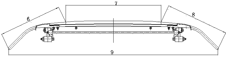
[0075] (b5) Measure the length of the bottom of the pantograph, the length of the left non-contact area, the length of the top of the bow, and the length of the right non-contact area in the pantograph image, such as image 3 As shown in the figure, 6 is the length of the left non-contact area, 7 is the...

Embodiment 3

[0079] Such as Figure 4 As shown, this embodiment limits the preprocessing on the basis of Embodiment 2. The preprocessing of this embodiment includes grayscale and binarization. Through grayscale processing, the color image captured by the infrared thermal imager Convert it into a gray-and-white image to compress the image capacity and double the image processing speed; perform binarization on the grayscaled image to obtain the following: Figure 5 The image shown, separates the background illumination and the real object, and plays a role in assisting recognition.


PUM


Abstract

The invention discloses a method for detecting contact net geometrical parameters based on infrared image processing. The method includes the following steps that firstly, an infrared thermal imager is installed on the top of a running locomotive and connected with a mainframe for processing and storing an infrared image; secondly, the infrared thermal imager is used for shooting an infrared image for a pantograph, the infrared image is used for making a pantograph model and relevant parameters of the pantograph model are measured; thirdly, wire height calibration is carried out on the infrared image shot by the infrared thermal imager; fourthly, the infrared thermal imager is used for collecting the positions of the pantograph continuously and transmitting the positions of the pantograph to the mainframe to be processed, the pantograph model matching calculation is carried out on the infrared image, the crossing point position between the current contact line and the pantograph is calculated out, and therefore the stagger value and the wire height are calculated out. The stagger value is the distance between the contact line and the center of the pantograph and the wire height is the vertical distance between the face of the pantograph and the top of the locomotive. By means of the method for detecting the contact net geometrical parameters based on infrared image processing, long-time stable working can be achieved, the anti-interference performance is achieved and in addition, cost can be reduced.

Description

technical field [0001] The invention relates to the field of parameter detection of a locomotive catenary, in particular to a method for detecting geometric parameters of a catenary based on infrared image processing. Background technique [0002] The geometric parameters of the catenary are one of the important indicators to evaluate the status of the catenary, and its working status directly affects the driving safety. At present, the following centralized methods are mainly used to calculate the geometric parameters of the catenary: [0003] 1. Contact type, by installing a sensor on the pantograph to measure the pull-out value of the catenary, and by installing an angular displacement encoder to measure the guide height, this method of contact measurement is generally installed on the inspection vehicle Or on the work vehicle (detection vehicle), because its own weight will affect the dynamic parameters of the pantograph, there are certain hidden dangers to driving safe...

Claims


Application Information

Patent Timeline
IPC IPC(8): G01B11/02
Inventor 范国海杨旭东李潇徐腊梅张辉
Owner CHENGDU NAT RAILWAYS ELECTRICAL EQUIP
Why Eureka
Try Eureka