


Quick Research
Generate reliable direction feasibility study reports for your R&D in just a few steps.

Technical Q&A
Discover and master advanced knowledge NOW. Basics, ideas, possibilities, all at once.

Find Solutions
As an expert in R&D theories, this can generate solutions to your technical problems instantly.

Evaluate Feasibility
Analyze your overall solution with one click, know your potential R&D risks in advance.

Monitor Landscape
Get weekly tech updates, stay abreast of the latest tech innovations and key insights.
Jacking mirror surface inspection mechanism for photovoltaic module laying platform
A photovoltaic module and module technology, applied in the direction of optical testing flaws/defects, can solve the problems of long distance from people, limited observation angle, inaccurate visual inspection, etc., to achieve the effect of large reflection angle, favorable mirror reflection, and strong practicability
- Summary
- Abstract
- Description
- Claims
- Application Information
AI Technical Summary
Problems solved by technology
Method used
Image

Examples
Embodiment Construction
[0019] The preferred embodiments of the invention will be described in detail below in conjunction with the accompanying drawings, so that the advantages and features of the invention can be more easily understood by those skilled in the art, so as to define the protection scope of the invention more clearly.
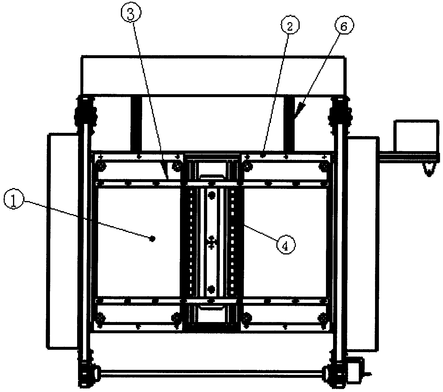
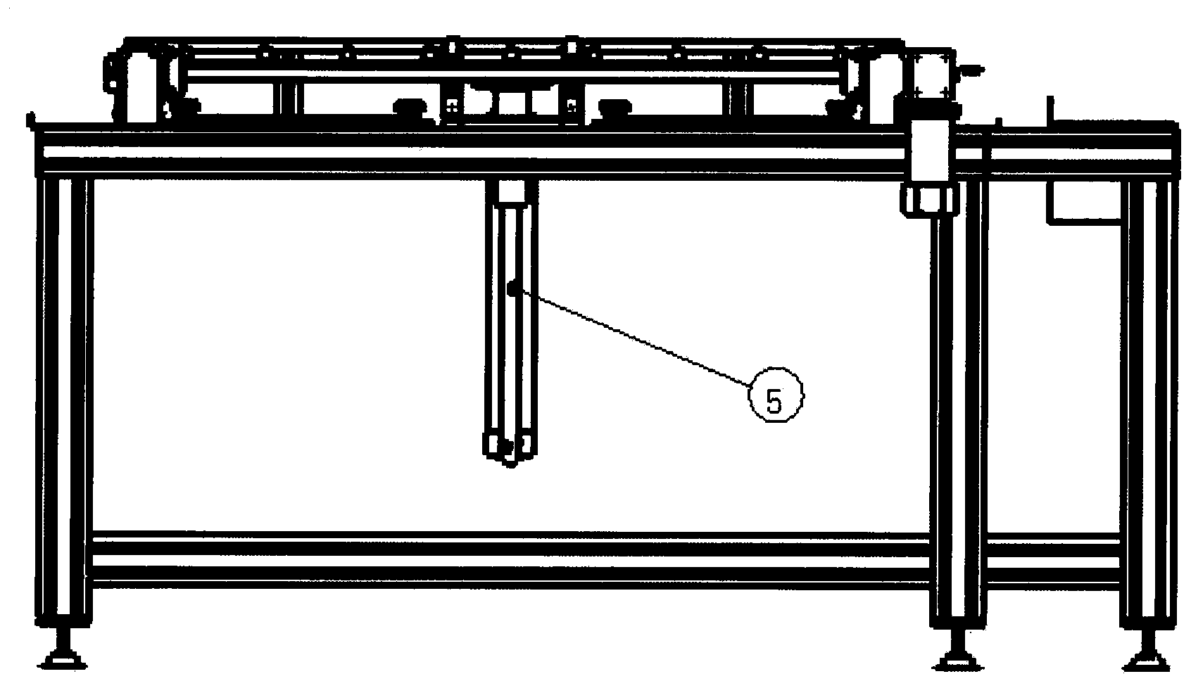
[0020] like figure 1 , figure 2 The shown-type photovoltaic module laying platform jacking mirror inspection mechanism includes 1 two mirrors, 2 two mirror tables, 3 a set of lifting brackets, 4 two wheel bars, 5 a jacking cylinder, 6 a pair of machines shelf. The role of the two mirrors in this mechanism is to visually inspect the components through the reflection of light. The component reaches a certain height at the same time through the lifting of the lifting bracket, forming a height difference between the component and the mirror surface, and completing the visual inspection of the component through the reflection of the mirror surface. The role of the roller...
PUM
 Abstract
Description
Claims
Application Information
 - R&D Engineer
- R&D Manager
- IP Professional
- Industry Leading Data Capabilities
- Powerful AI technology
- Patent DNA Extraction
Browse by: Latest US Patents, China's latest patents, Technical Efficacy Thesaurus, Application Domain, Technology Topic, Popular Technical Reports.
© 2024 PatSnap. All rights reserved.Legal|Privacy policy|Modern Slavery Act Transparency Statement|Sitemap|About US| Contact US: help@patsnap.com