A busbar protection method based on the sudden change direction of fault current in the power frequency band

A technology for fault current and busbar protection, which is applied in the direction of the fault location, etc., to achieve the effect required by the reliable sampling rate of protection

Active Publication Date: 2017-02-15
KUNMING UNIV OF SCI & TECH
View PDF10 Cites 0 Cited by
  • Summary
  • Abstract
  • Description
  • Claims
  • Application Information

AI Technical Summary

Problems solved by technology

Use the short-time window data after the fault and judge the polarity of the frequency band where the power frequency is located to overcome the impact of current busbar protection that is affected by CT saturation, current power frequency flowing out of the faulty bus, and the need to detect traveling waves.

Method used


Image

  • A busbar protection method based on the sudden change direction of fault current in the power frequency band
  • A busbar protection method based on the sudden change direction of fault current in the power frequency band
  • A busbar protection method based on the sudden change direction of fault current in the power frequency band

Examples


Embodiment 1

[0044] Embodiment 1: A busbar protection method based on the sudden change direction of the fault current in the power frequency band. When the busbar or the line fails, the three-phase current data of each line on the busbar within the short time window after the fault is extracted, and passed through the three-phase The current data is calculated to obtain the line-mode current including the fault phase; the db4 wavelet transform is performed on the line-mode current, and the frequency band where the power frequency is located is used for straight line fitting. According to whether the polarity of the line slopes obtained by fitting the lines is the same, it is judged that it is a bus Fault or wiring fault.

[0045] The specific steps of the method are:

[0046] (1) When the bus or line fails, the measuring unit reads 2τ min Current data in the time window, τ min is the time for the traveling wave to propagate through the full length on the shortest outgoing line connected...

Embodiment 2

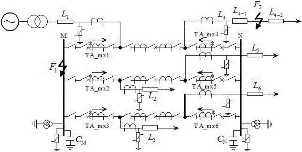
[0055] Embodiment 2: with figure 1 Take the simulation system of , as an example, the system is a 3 / 2 connection mode, and TA_mxi (i=1, 2, 3, 4, 5, 6) is the i-th current transformer. The sampling frequency is 20kHz, and F1 and F2 are set as phase A metal ground faults, and the initial fault angle is 90°. Line L 4 Fault, the length of the shortest outgoing line connected to the busbar in the simulation system is 180km, calculated from 2τmin=2lmin / v to get 2τmin=1.2ms.

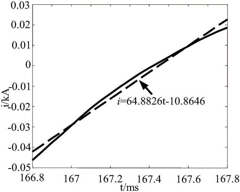
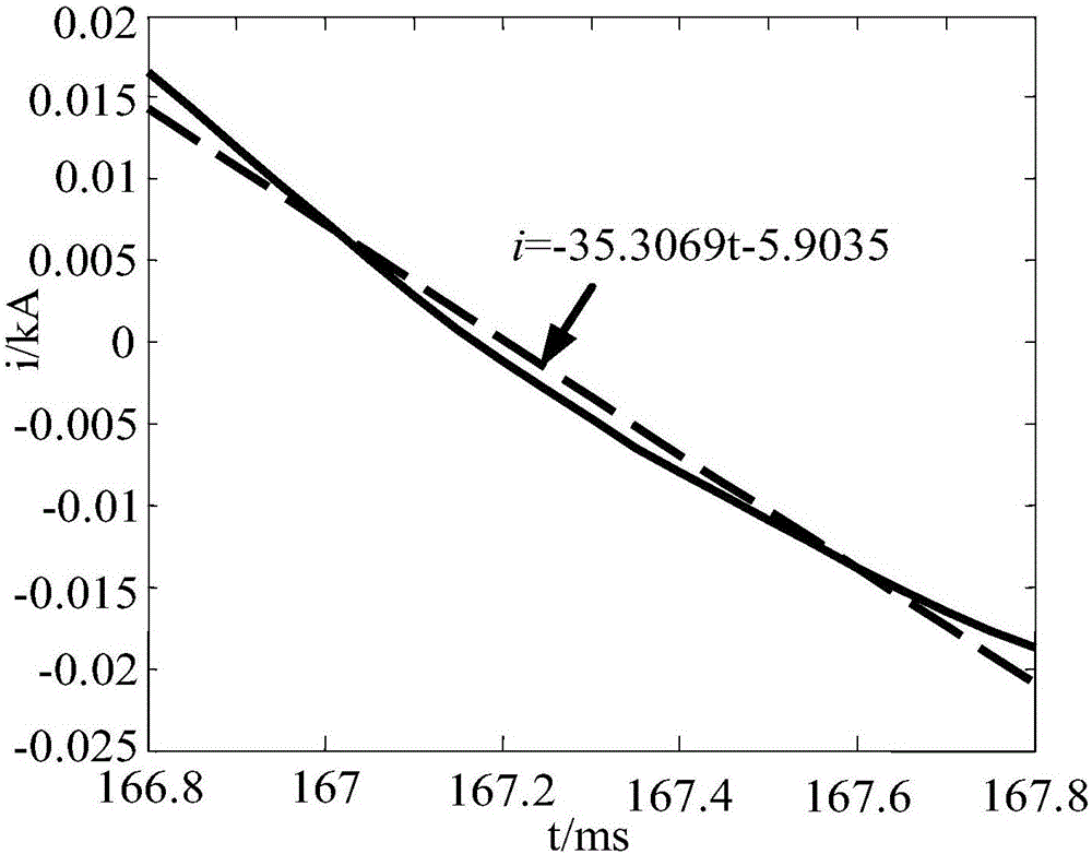
[0056] The linear fitting result of the initial current waveform under the power frequency band is calculated as figure 2 with image 3 shown.

[0057] From the simulation results, it can be seen that the slope of the straight line obtained by fitting the data of the frequency band where the fault current power frequency quantity is: a 1 =64.8826, a 2 =-35.3069,a 3 =-26.4415. According to formula (1), it can be seen that the calculation result is G M = 0, it is judged as a line fault, consistent with ...

Embodiment 3

[0058] Embodiment 3: Still with figure 1 Take the simulation system of , as an example, the system is a 3 / 2 connection mode, and TA_mxi (i=1, 2, 3, 4, 5, 6) is the i-th current transformer. The sampling frequency is 20kHz, and F1 and F2 are set as phase A metal ground faults, and the initial fault angle is 90°. When a bus failure occurs, the length of the shortest outgoing line connected to the bus in the simulation system is 180km, and 2τmin=1.2ms is calculated by 2τmin=2lmin / v.

[0059] The linear fitting result of the initial current waveform under the power frequency band is calculated as Figure 4 with Figure 5 shown.

[0060] From the simulation results, it can be seen that the slope of the straight line obtained by fitting the data of the frequency band where the fault current power frequency quantity is: a 1 =-130.7087,a 2 =-390.3307,a 3 =-337.0287. Also according to formula (1), it can be seen that the calculation result is G M = 1, it is judged as a bus faul...


PUM


Abstract

The invention discloses a bus protection method based on the sudden-change direction of fault current containing power frequency bands, and belongs to the technical field of power system relay protection. When a bus or a circuit breaks down, three-phase current data of all circuits of the bus in a short time window existing after the bus or the circuit breaks down are extracted, and a line model current containing fault phases is obtained after calculation through the three-phase current data; db4 wavelet transform is conducted on the line model current, the frequency bands where power frequency amount exists are used for conducting straight line fitting, and whether the bus breaks down or the circuit breaks down is judged according to whether the slope polarities of straight lines obtained through fitting of all the circuits are the same or not. According to the bus protection method based on the sudden-change direction of the fault current containing power frequency bands, protection is formed by means of the variation tendency of power frequency band components of the current, the protection is reliable, the requirement for the sampling rate is low, and the head polarity of traveling waves does not need to be detected; the needed time window is short, the complete power frequency amount does not need to be extracted, the situations where a current transformer is saturated, and a power frequency current flows out of the fault bus cannot influence the method.

Description

technical field [0001] The invention relates to a busbar protection method based on a sudden change direction of a fault current in a power frequency band, and belongs to the technical field of electric power system relay protection. Background technique [0002] The busbar protection mainly uses Kirchhoff's current theorem to judge whether the busbar is faulty. When the sum of the currents on the lines connected to the busbar is 0, the busbar is not faulty. Otherwise, it is a busbar fault. When a large current flows through the line, the current transformer (CT) that measures the current will be saturated, resulting in a difference between the measured current waveform and the actual current waveform, causing the sum of the currents on each line calculated by the busbar protection to be non-zero . In order to avoid the impact of current transformer saturation on busbar protection, the current data before saturation can be used to judge whether the busbar is faulty or not, ...

Claims


Application Information

Patent Timeline
Patent Type & Authority Patents(China)
IPC IPC(8): G01R31/08
Inventor 束洪春曹璞璘高利郭小兵
Owner KUNMING UNIV OF SCI & TECH
Why Eureka
Try Eureka