A PLC type optical power splitter with adjustable power division ratio and its preparation method and adjustment method

An optical power splitter and adjustment method technology, applied in optics, instruments, nonlinear optics, etc., can solve the problems of high design difficulty, high nonlinearity, poor thermal stability of polymers, etc., and achieve finely adjustable power division ratio, The effect of low driving voltage and simple structure

Active Publication Date: 2016-04-13
SOUTHEAST UNIV
View PDF7 Cites 0 Cited by
  • Summary
  • Abstract
  • Description
  • Claims
  • Application Information

AI Technical Summary

Problems solved by technology

Ordinary PLC optical power splitters can only provide a fixed power split ratio, and the existing new PLC optical power splitter material systems with adjustable power split ratios are mostly based on materials such as indium phosphide or polymers, among which the price of indium phosphide It is more expensive and has high nonlinearity, but the thermal stability of the polymer is poor; the commonly used modulation method is to add modulation modules on both sides of the Y branch or use the principle of multi-mode interference, in which the structure of the modulation module is added to both outputs of the Y branch. The design of the mode interference principle is more difficult

Method used


Image

  • A PLC type optical power splitter with adjustable power division ratio and its preparation method and adjustment method
  • A PLC type optical power splitter with adjustable power division ratio and its preparation method and adjustment method
  • A PLC type optical power splitter with adjustable power division ratio and its preparation method and adjustment method

Examples


preparation example Construction

[0046] The preparation method of the above-mentioned power split ratio adjustable PLC type optical power splitter comprises the following steps:

[0047] Step 10): Take a silicon substrate 1 and clean the silicon wafer by wet chemical method;

[0048] Step 20): preparing a silicon dioxide buffer layer 2 on the silicon substrate 1 by thermal oxidation;

[0049] Step 30): Doping germanium dioxide into the silicon dioxide buffer layer 2 by using a plasma-enhanced chemical vapor deposition method to obtain a waveguide layer 3;

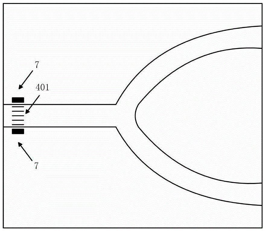
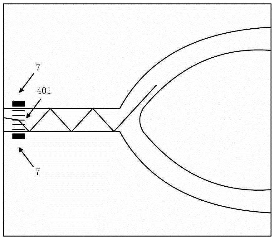
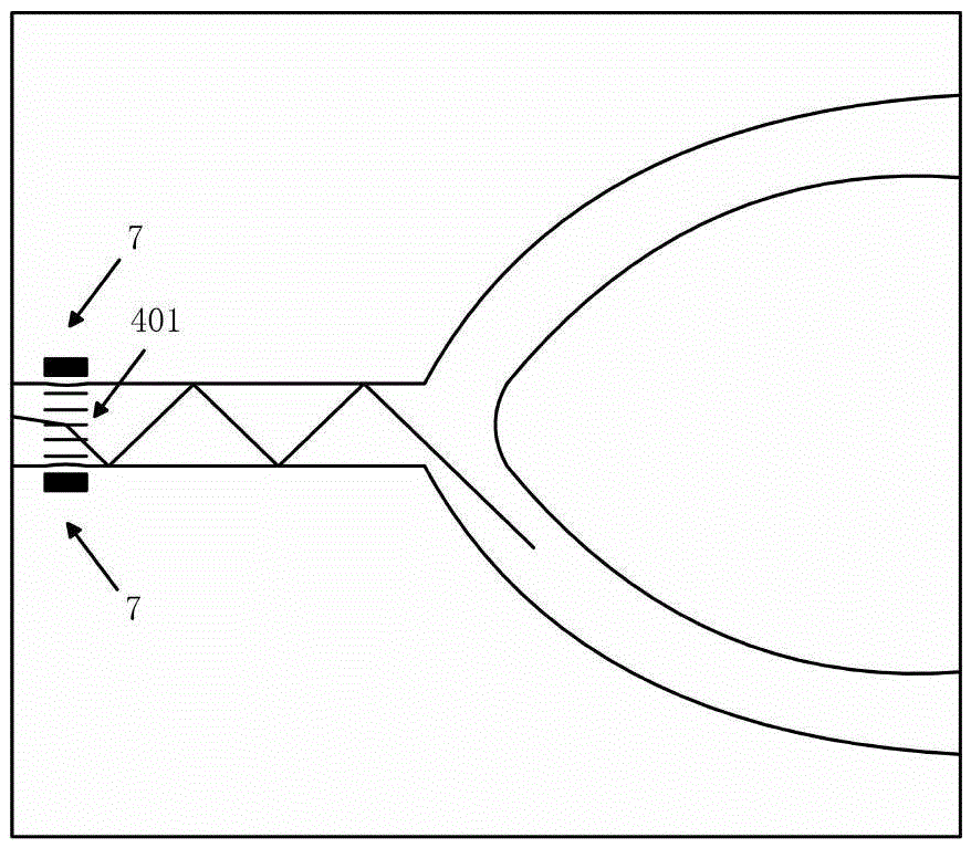
[0050] Step 40): using photolithography and etching process to prepare waveguide 4 on waveguide layer 3, waveguide 4 includes n-level shunt structure, and i-th-level shunt structure includes 2 i-1 branching units, and each branching unit is Y-shaped, each branching unit includes an input waveguide and two output waveguides, and each branching unit is provided with a waveguide grating 401;

[0051] Step 50): using a high-temperature annealing process to g...

Embodiment 1

[0061] Such as figure 1 As shown, a PLC type 1×2 optical power splitter with adjustable power division ratio adopts a planar light wave optical circuit PLC chip, and the planar light wave optical circuit PLC chip includes a silicon substrate 1 and a silicon dioxide buffer grown on the silicon substrate 1 Layer 2, a waveguide 4 grown on the silicon dioxide buffer layer 2, a cover layer 5 grown on the waveguide 4, two electrodes 7 deeply etched on the cover layer 5, the waveguide 4 includes a 1-level Y-shaped shunt structure, A level 1 shunt structure consists of a shunt unit. One input waveguide of the branching unit is the input end of the power splitter, and the two output waveguides are the output ends of the power splitter. A waveguide grating 401 is arranged on the input waveguide, and electrodes 7 are deeply etched on both sides of the waveguide grating 401 . The power divider applies different intensities of driving voltage to the electrostatic adjustable grating, chan...

Embodiment 2

[0063] Introduce the preparation method of embodiment 1 optical power splitter below, this preparation method comprises the following steps:

[0064] Step 10): making the silicon dioxide buffer layer 2 and the waveguide 3 . refer to Figure 4 As shown, it includes step 101), step 102) and step 103).

[0065] Step 101) Take a silicon substrate 1, use a wet chemical method to clean the silicon wafer as the silicon substrate 1, and remove the dirt on the surface; then, after ultrasonic cleaning and drying with deionized water, the cleaning of the silicon wafer is completed;

[0066] Step 102) Prepare the silica buffer layer 2. There are many methods for preparing the silica buffer layer 2, such as chemical vapor deposition (CVD), flame hydrolysis (FHD), sol-gel method (Sol-Gel), Thermal oxidation (TO), etc. Since the thermal oxidation method can oxidize hundreds of silicon wafers at the same time, it has high efficiency in actual production, and can simultaneously oxidize the ...


PUM

PropertyMeasurementUnit
thicknessaaaaaaaaaa
thicknessaaaaaaaaaa

Abstract

The invention discloses a PLC type optical power divider with the adjustable power division ratio. A PLC chip is adopted, and the PLC chip comprises a silicon substrate, a silicon dioxide buffer layer, a waveguide, a covering layer and 2<n+1>-2 electrodes arranged on the covering layer in an etching mode. The waveguide comprises n stages of shunt structures, the ith shunt structure comprises 2<i-1> shunt units, each shunt unit is in the shape of Y and comprises an input waveguide and two output waveguides, each shunt unit is provided with a waveguide grating, and the electrodes are arranged on the two sides of the waveguide gratings. The power division ratio of the optical power divider can be fine adjusted. The invention further provides a manufacturing method of the optical power divider. The manufacturing method is simple, low in cost and capable of being used for batch production. The invention further provides an adjusting method of the optical power divider, and thus the power division ratio can be accurately adjusted.

Description

technical field [0001] The invention belongs to the technical field of integrated photonic devices, and specifically relates to a PLC-type optical power splitter with adjustable power division ratio, a preparation method and an adjustment method. Background technique [0002] The optical power splitter is one of the core devices connecting the optical line terminal and the optical network unit. There are two main manufacturing techniques: one is the fused tapered fiber splitter produced by traditional optical passive device manufacturing technology (tapered coupling method); the other is the planar waveguide type ( PLC) type optical power splitter. [0003] The traditional fused tapered fiber splitter has simple structure, small size, light weight, corrosion resistance, high sensitivity, and strong anti-electromagnetic interference ability, but it is greatly affected by the temperature environment, resulting in low system performance stability, and the traditional fusion T...

Claims


Application Information

Patent Timeline
Patent Type & Authority Patents(China)
IPC IPC(8): G02F1/01G02B6/13
Inventor 孙小菡蒋卫锋戚健庭潘超陈源源董纳
Owner SOUTHEAST UNIV
Why Eureka
Try Eureka