Simple and high-efficiency relay matrix plate
A relay matrix and relay array technology, which is applied in the direction of instruments, simulators, computer control, etc., can solve the problems of high maintenance costs, increased costs, unfavorable production, etc., and achieve the effect of multiple matrix channels, convenient maintenance, and reliable performance
- Summary
- Abstract
- Description
- Claims
- Application Information
AI Technical Summary
Problems solved by technology
Method used
Image

Examples
Embodiment Construction
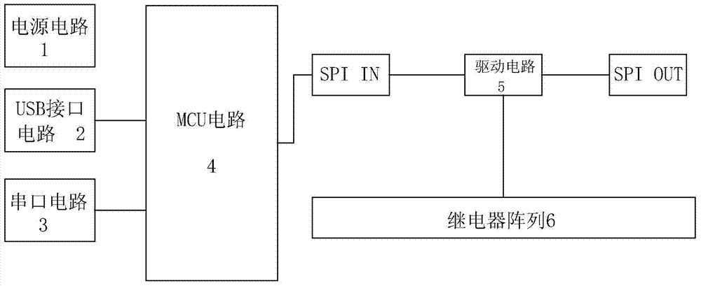
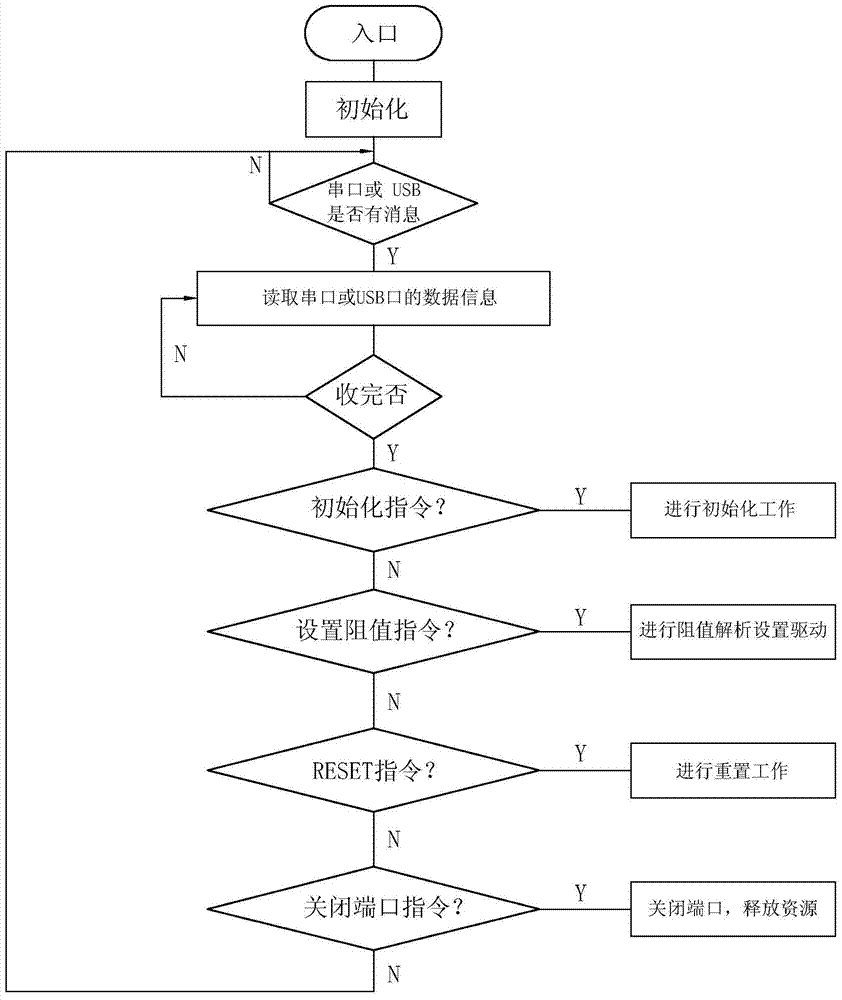
[0012] refer to Figure 1-Figure 2 , the specific embodiment adopts the following technical scheme: it comprises power supply circuit 1, USB interface circuit 2, serial port circuit 3, MCU circuit 4, drive circuit 5 and relay array 6, USB interface circuit 2, serial port circuit 3 are all connected with MCU circuit 4 Connection, MCU circuit 4 is connected with drive circuit 5 through SPI IN interface, drive circuit 5 is connected with SPI OUT interface, relay array 6 respectively, power supply circuit 1 and USB interface circuit 2, serial port circuit 3, MCU circuit 4, drive circuit 5 and The relay array 6 is connected to power it.
[0013] The drive circuit 5 adopts a Darlington tube ULN2803 to improve the driving ability, and at the same time it plays a role of circuit isolation, and the TVS tube eliminates the influence of the reverse electromotive force generated by the relay at the moment of power failure on other components.
[0014] The relay array 6 adopts 2*32, and t...
PUM
 Abstract
Description
Claims
Application Information
 - R&D
- Intellectual Property
- Life Sciences
- Materials
- Tech Scout
- Unparalleled Data Quality
- Higher Quality Content
- 60% Fewer Hallucinations
Browse by: Latest US Patents, China's latest patents, Technical Efficacy Thesaurus, Application Domain, Technology Topic, Popular Technical Reports.
© 2025 PatSnap. All rights reserved.Legal|Privacy policy|Modern Slavery Act Transparency Statement|Sitemap|About US| Contact US: help@patsnap.com