
Chain links with hinge and fork segments separated by sliding segments

A sliding segment and chain link technology, applied in the field of chain links, can solve the problems of expensive materials and achieve the effect of eliminating screams

Active Publication Date: 2016-05-11
ROBERT BOSCH GMBH
View PDF8 Cites 0 Cited by
  • Summary
  • Abstract
  • Description
  • Claims
  • Application Information

AI Technical Summary

Problems solved by technology

But this material is very expensive

Method used


Image

  • Chain links with hinge and fork segments separated by sliding segments
  • Chain links with hinge and fork segments separated by sliding segments
  • Chain links with hinge and fork segments separated by sliding segments

Examples


Embodiment Construction

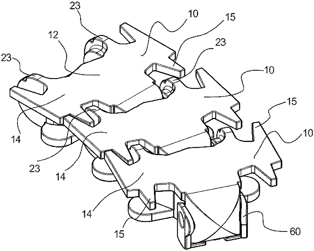
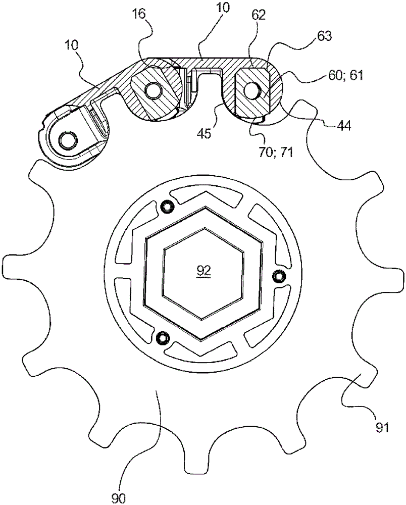
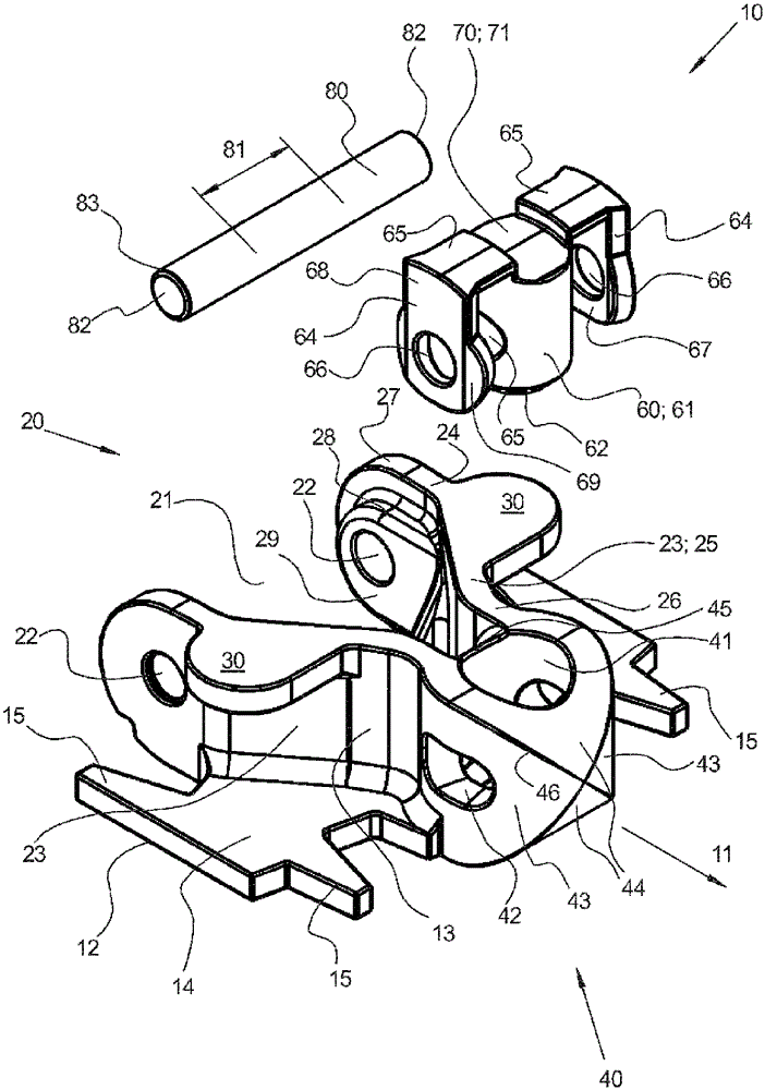
[0025] figure 1 An exploded view of a chain link 10 according to the invention is shown. Chain link 10 comprises a one-piece base body 13 made of polyoxymethylene, a one-piece articulation part 60 made of polyamide and a bolt 80 made of steel. The base body 13 and the hinge member 60 are respectively made by plastic die-casting.

[0026] The base body 13 , which is generally mirror-symmetrical, comprises an articulation section 40 and a fork section 20 as well as a carrying means 14 . The carrying means is embodied in the form of a plate which defines a transport plane 12 . The plate 14 is provided with teeth 15 pointing in the conveying direction 11, so that the teeth 15 of adjacent base bodies 13 of a conveyor chain engage with each other, so that the (not shown) conveyed goods are as far as possible even when traveling in curves. supported on the surface. The flat plate 14 is arranged so close to the articulation section 40 and the fork section 20 that it does not trans...


PUM


Abstract

A chain link for a curved conveyor chain, the chain link comprising a base body and a bolt, the base body having an articulation section and a fork section and a carrier means for carrying material that is to be conveyed, the bolt being elongated and designed in a circular cylindrical manner in at least one central section. In the articulation section, a bolt opening is provided through which the bolt can pass and can rotate relative to at least two axes. The fork section has an articulation recess for receiving the articulation section of an adjoining identical chain link, the fork section having two opposite bolt recesses which can receive the opposite ends of the bolt of the adjoining chain link. The articulation and fork sections of two adjoining, identical chain links are maintained at a distance by two slide sections.

Description

technical field [0001] The invention relates to a chain link for a curved conveyor chain. Background technique [0002] A chain link for a curved conveyor chain is known from DE 1010027229 A1. according to figure 1 and 2 , the chain link includes a base and a (not shown) bolt. The one-piece base body comprises a hinge section 10 and a fork section 11 . A carrying means in the form of a flat support surface 3 is arranged on the upper side of the base body, with which the conveyed goods (not shown) can be carried with a friction fit. Instead of a flat support surface, other carrying means are also known, such as levers, friction discs or brushes protruding perpendicularly to the support surface. In combination with the carrier means shown last, a multi-part base body is often provided. [0003] The screw is elongated, wherein it is cylindrical over its entire length. A screw passage 9 is provided in the joint section, through which the screw is rotatable about two axes....

Claims


Application Information

Patent Timeline
Patent Type & Authority Patents(China)
IPC IPC(8): B65G17/08
CPCB65G17/086B65G15/30B65G17/40B65G2201/02
Inventor T.居纳W.拜尔P.路德维希H-P.布陶
Owner ROBERT BOSCH GMBH
Learn More