
Direct-drive wind turbine

A wind turbine, driven technology, applied in the direction of wind turbines, wind turbine components, engines, etc., can solve the problems of large pads, heavy pads, difficult to replace, etc., to achieve energy saving, bearing manufacturing more efficient, and optimize wear effects

Inactive Publication Date: 2014-04-30
SIEMENS AG
View PDF5 Cites 18 Cited by
  • Summary
  • Abstract
  • Description
  • Claims
  • Application Information

AI Technical Summary

Problems solved by technology

As a result, pads for cylindrical bearing surfaces are very large, heavy and difficult to exchange

Method used


Image

  • Direct-drive wind turbine
  • Direct-drive wind turbine

Examples


Embodiment Construction

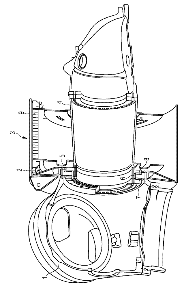
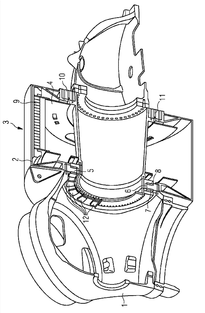
[0068] figure 1 A longitudinal section through the hub 1 , plain bearing 5 and generator 3 of a direct drive wind turbine is shown. The longitudinal section is taken along the axis of rotation of the generator 3 of the wind turbine.

[0069] The hub 1 is connected to the rotor 2 of the generator and to the rotating side of the bearing 5 . The stator 9 of the generator 3 and the fixed side 4 of the wind turbine are connected to the fixed side of the slide bearing 5 .

[0070] A plain bearing 5 is located between the hub 1 of the wind turbine and the generator 3 of the wind turbine. It is connected with the fixed side to the hub-side end of the stator 9 of the generator 3 and with the rotating side to the hub 1 of the wind turbine.

[0071] The plain bearing 5 rotatably connects the rotating drive train of the wind turbine with the stator 9 of the generator and the stationary part 4 of the wind turbine.

[0072] The rotating drive train comprises a hub 1 of the wind turbine ...


PUM


Abstract

The invention relates to a direct-drive wind turbine and the main bearing used in such a wind turbine. The rotating drive train is connected with a stationary part of the wind turbine via at least one bearing (5), which allows the rotation of the drive train in relation to the stationary part. The at least one bearing (5) is a plain bearing; the bearing comprises at least one cylindrical sliding surface (6) constructed to support radial loads present in the drive train. The bearing comprises at least two radial bearing surfaces (7, 8) constructed to support axial loads and bending moments present in the drive train. The surface areas of the radial bearing surfaces (7, 8) are dimensioned proportional to a predetermined maximum total load of the bending moments expected in the drive train.

Description

technical field [0001] The present invention relates to direct drive wind turbines, and main bearings used in such wind turbines. Background technique [0002] Wind turbines convert the energy of moving air into electricity. The moving air accelerates the rotor of the wind turbine. The rotation of the rotor is transmitted to the generator. Generators convert rotational energy into electrical energy. [0003] In the last few years, the concept of direct drive wind turbines has been created. In a direct drive wind turbine, the rotational energy of the rotor is transferred directly to the generator without the use of a gearbox. [0004] In a direct drive wind turbine, the rotor of the wind turbine is directly connected to the rotor of the generator. The chain of mechanically connected parts leading from the rotor of the wind turbine to the rotor of the generator is called the drive train of the wind turbine. [0005] To allow rotational movement and provide the required s...

Claims


Application Information

Patent Timeline
Patent Type & Authority Applications(China)
IPC IPC(8): F03D11/00F16C17/10
CPCF16C17/10F03D11/028Y02E10/725Y02E10/722F03D11/0008F05B2220/7066F03D15/20F03D80/70F16C17/107F16C33/046F16C33/586F16C2231/00F16C2300/14F16C2360/31F16C2380/26Y02E10/72
Inventor B.佩德森K.汤姆森
Owner SIEMENS AG
Learn More