finned heat exchanger

A technology for heat exchangers and fins, applied in the field of heat exchangers, can solve the problems of increased ventilation resistance, increased fan performance, reduced performance, etc., and achieves the advantages of suppressing the generation of abnormal sound, improving heat exchange performance, and uniformizing wind speed distribution. Effect

Active Publication Date: 2016-11-16
PANASONIC CORP
View PDF8 Cites 0 Cited by
  • Summary
  • Abstract
  • Description
  • Claims
  • Application Information

AI Technical Summary

Problems solved by technology

[0010] However, in a heat exchanger with such a structure, the ventilation resistance at the portion where three rows of heat transfer tubes are arranged increases, and the wind speed distribution of the heat exchanger becomes uneven, which may lead to a decrease in performance.
Moreover, in image 3 In the structure of the conventional heat exchanger shown, the wind speed distribution near the cross-flow fan is not uniform, which promotes the generation of strange sounds proportional to the product of the number of blades of the fan and the operating speed, and may cause large noise. noise

Method used


Image

  • finned heat exchanger
  • finned heat exchanger
  • finned heat exchanger

Examples


Embodiment approach 1

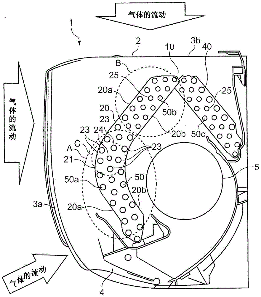
[0059] First, based on figure 1 The indoor unit of the air conditioner equipped with the finned heat exchanger of Embodiment 1 is demonstrated. figure 1 It is a longitudinal sectional view of the indoor unit equipped with the finned heat exchanger of Embodiment 1.

[0060] Such as figure 1 As shown, suction ports 3a and 3b are provided on the front surface and the upper surface of the housing 2 of the indoor unit 1 of this air conditioner, and an air outlet 4 is provided on the lower surface. exist figure 1 , for the gas that is sucked into the shell 2, the general direction of flow is shown by the arrow. A cross-flow fan 5 and a finned heat exchanger 10 are housed inside the casing 2 .

[0061] The finned heat exchanger 10 is arranged on the front side in the case 2 and includes a front side heat exchanger 20 formed in a convex shape so as to protrude toward the front side and a back side arranged on the back side in the case 2 . Heat exchanger 40. In addition, the ...


PUM


Abstract

The finned heat exchanger of the present invention, in order to substantially uniformize the wind speed distribution of the heat exchanger and improve heat exchange performance, includes a heat transfer tube (50) through which refrigerant flows and a plurality of first heat transfer tubes inserted into the heat transfer tubes. A stack of fins (21) of a fin collar (23), a plurality of first fin collars are arranged in a plurality of rows along a direction substantially orthogonal to the flow direction of the gas, and second fin collars that are not inserted into the heat transfer tube The fin collars (24) are arranged between the first fin collars arranged in multiple rows.

Description

technical field [0001] The present invention relates to a finned heat exchanger installed in an indoor unit of an air conditioner. Background technique [0002] Generally in the indoor unit of the air conditioner, such as figure 2 As shown, the casing 101 is provided with one or more suction ports such as a front suction port 102a and an upper surface suction port 102b, and one or more blowing ports such as a plurality of blowing ports 103 divided into a lower surface. A cross-flow fan 105 and finned heat exchangers 104A, 104B, 104C, and 104D are housed in the casing 101 (for example, refer to patent documents). [0003] In the conventional air conditioner configured in this way, the finned heat exchanger 104 is disposed on the front side in the casing 101 . The finned heat exchanger 104 includes: two front side heat exchangers 104A, 104A bent in the vicinity of the center portion in the vertical direction; ; and auxiliary heat exchangers 104C, 104D attached to the respec...

Claims


Application Information

Patent Timeline
Patent Type & Authority Patents(China)
IPC IPC(8): F24F13/30F24F1/00F28F1/32F24F1/0063F24F1/0067
CPCF28F1/325F24F1/0057F24F1/0067F24F1/0063
Inventor 横山昭一
Owner PANASONIC CORP
Why Eureka
Try Eureka