
Extractor hood

A range hood and fan technology, applied in the field of range hoods, can solve the problems of smoke running out of the air inlet, poor effect of range hood, and reduced effect of range hood, and achieve the effect of uniform distribution of wind speed

Pending Publication Date: 2018-07-03
NINGBO FOTILE KITCHEN WARE CO LTD
View PDF1 Cites 1 Cited by
  • Summary
  • Abstract
  • Description
  • Claims
  • Application Information

AI Technical Summary

Problems solved by technology

Although the near-suction range hood can make the noise of the range hood smaller and the oil separation degree higher under the premise that the air volume is not affected, the fan adopts a single air inlet mode, and the negative pressure area exists in the middle of the air inlet. Disadvantages of large size and small size on both sides, there is smoke running on both sides of the air inlet, and the oil suction effect on both sides is poor
In addition, if the air inlet of the existing near-suction range hood is designed as a wide-area air inlet, the air inlet speed at both ends of the air inlet will drop significantly, thereby greatly reducing the effect of the range hood.

Method used


Image

  • Extractor hood
  • Extractor hood
  • Extractor hood

Examples


Embodiment 1

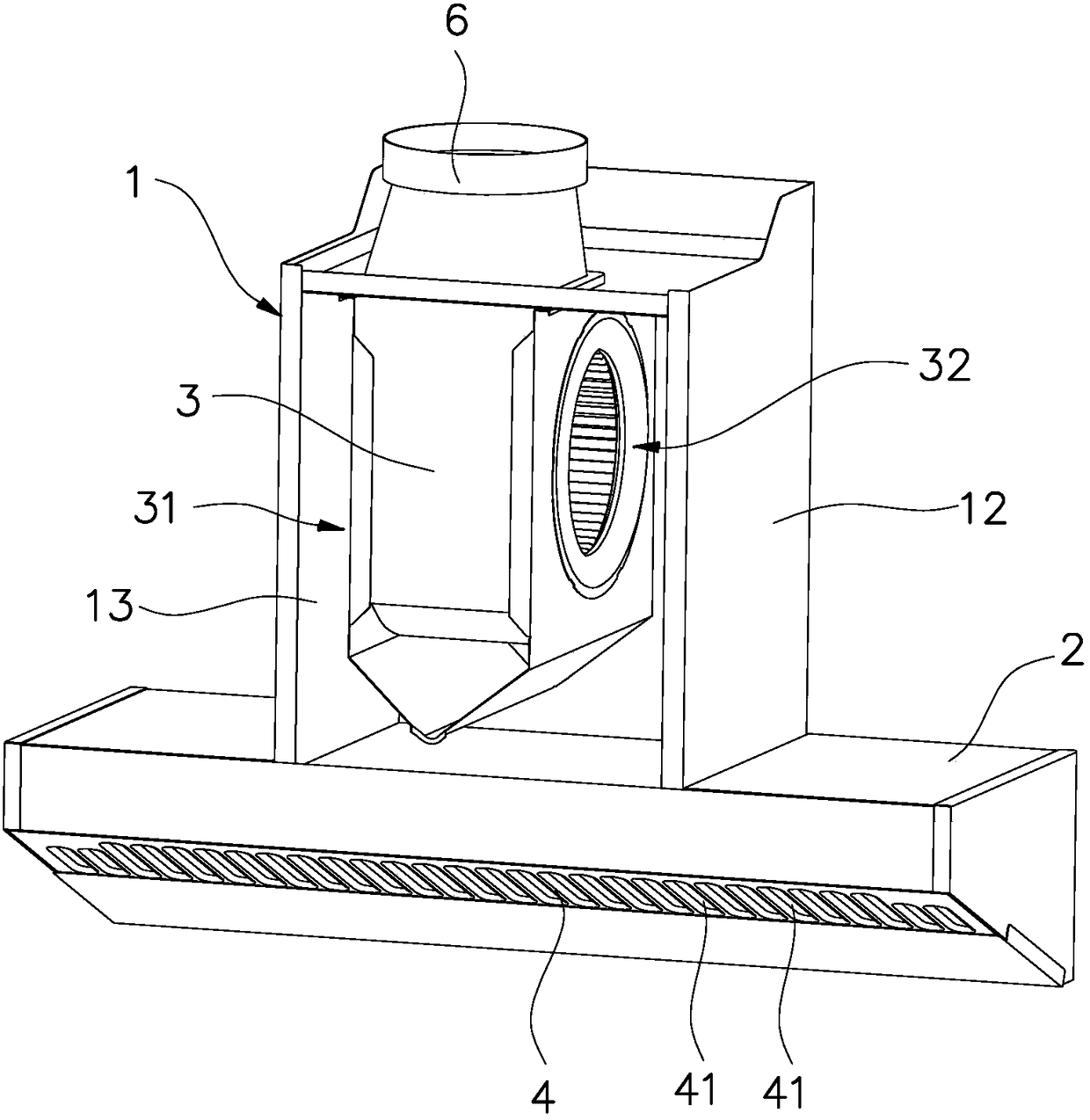
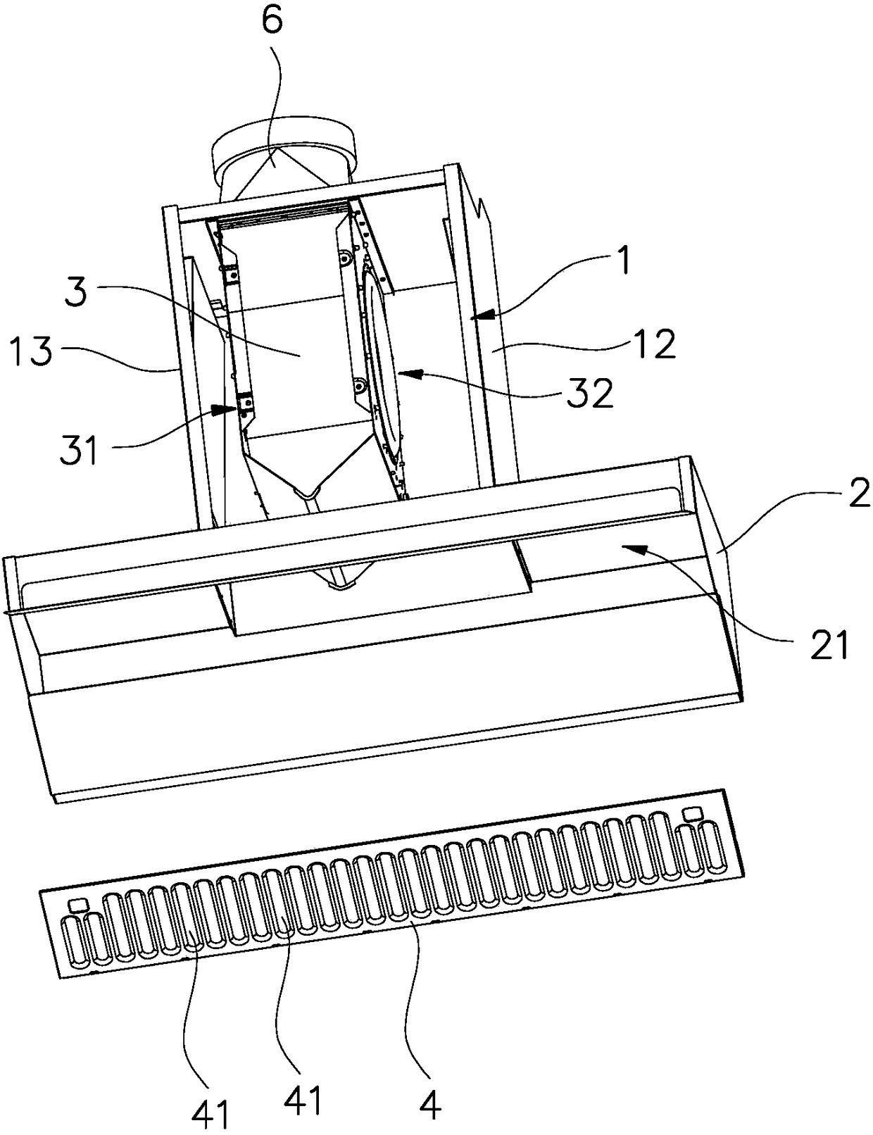
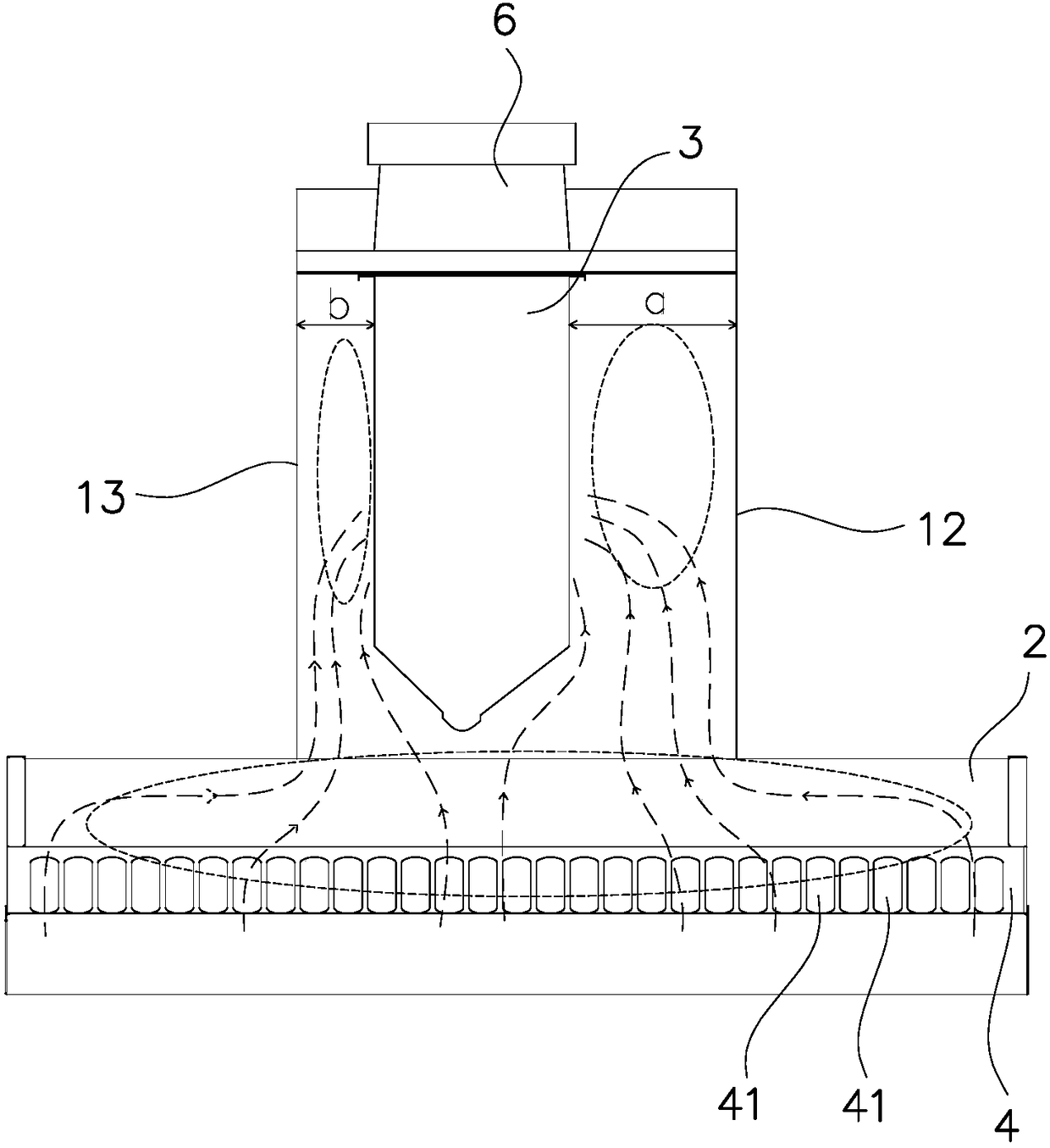
[0024] like Figure 1 to Figure 3 As shown, the range hood in this embodiment is a near-suction type range hood, which includes a fan housing 1, a smoke collection hood 2, a centrifugal fan 3, a first oil filter plate 4 and other components. Wherein, the smoke collecting hood 2 is arranged under the fan cover 1, and the inside of the fan cover 1 and the smoke collecting hood 2 together form a T-shaped inner cavity. The two ends are respectively adjacent to the corresponding sides of the smoke collecting hood 2, and the length of the wide air inlet 21 reaches about 1 meter. The first oil filter plate 4 is installed at the wide air inlet and its shape is adapted to the wide air inlet 21 . In addition, the range hood is equipped with an air outlet cover 6 connected to the air outlet of the centrifugal fan on the top of the fan housing 1 .

[0025] The centrifugal fan 3 of this embodiment is vertically installed in the fan housing 1 , and the central axis of the impeller 34 of t...

Embodiment 2

[0029] like Figure 4 to Figure 7 As shown, the range hood of this embodiment is a near-suction type range hood, the centrifugal fan 3 is biased left and right, the motor 33 of the centrifugal fan 3 is installed on the left side of the fan, and the left air inlet 31 of the fan is a secondary air inlet. The air inlet 32 ​​on the right side is the main air inlet, and the smoke collecting hood 2 also adopts the wide air inlet 21. Compared with Embodiment 1, this embodiment adds a second oil filter plate 5, the second oil filter plate 5 is installed in the middle of the back of the first oil filter plate 4, and the second oil filter plate 5 is located at the side of the wide air inlet 21 In the middle, and the left and right width of the second oil filter plate 5 is equal to or smaller than the width of the fan housing 1 .

[0030] In the present embodiment, the first oil filtering holes 41 are formed on the first oil filtering plate 4 in order from left to right, and the length ...


PUM


Abstract

The invention discloses an extractor hood. The extractor hood comprises a fan cover and a smoke collecting hood arranged under the fan cover. A centrifugal fan is arranged in the fan cover. The extractor hood is characterized in that the fan cover and the interior of the smoke collecting hood form a T-shaped inner cavity, the centrifugal fan is provided with a left air inlet and a right air inlet,the lower part of the smoke collecting hood forms a wide air inlet, the left and right ends of the wide air inlet are respectively close to the corresponding sides of the smoke collecting hood, and afirst oil filtering plate with a matched shape is arranged at the wide air inlet. The fan cover and the interior of the smoke collecting hood form the T-shaped inner cavity negative pressure expansion area and fit to the centrifugal fan with left and right air inlets and the wide air inlet of the smoke collecting hood so that the negative pressure area distance is increased along a left-right direction and the negative pressure area is increased and thus the negative pressure area actually used by the user can cover the whole kitchen range operation space. An air rate at the air inlet is uniform and the noise is effectively reduced.

Description

technical field [0001] The invention relates to a range hood. Background technique [0002] The current near-suction range hoods are all developing in the direction of reducing noise, increasing air volume, and improving grease separation. However, noise, air volume, and grease separation are a pair of contradictory factors. Simply by increasing the motor power and speed, Although the air volume can be increased, the noise will inevitably be greater, and the power consumption will be greater, and the denser oil filter screen alone can make the grease separation higher, but this will also increase the wind resistance and affect the air quality. The air volume will also increase the noise. Therefore, the general range hood can only seek a compromise point in the relationship between the three, taking into account the effects of the three aspects, or only make two of the factors stand out, while sacrificing the third factor. For example, the "near-suction range hood" disclose...

Claims


Application Information

Patent Timeline
Patent Type & Authority Applications(China)
IPC IPC(8): F24C15/20
CPCF24C15/2035
Inventor 施旭娜袁柯铭朱逸唐兴旺茅忠群诸永定李斌
Owner NINGBO FOTILE KITCHEN WARE CO LTD
Learn More