Dehumidifier

A technology for dehumidifiers and cabinets, which is applied in household heating, lighting and heating equipment, space heating and ventilation, etc. It can solve problems such as uneven wind speed distribution, poor dehumidification performance, and large system resistance, and achieve increased dehumidification performance. , increase the air volume, improve the effect of energy efficiency

Inactive Publication Date: 2010-03-31
LG ELECTRONICS (TIANJIN) APPLIANCES CO LTD
View PDF0 Cites 1 Cited by
  • Summary
  • Abstract
  • Description
  • Claims
  • Application Information

AI Technical Summary

Problems solved by technology

[0005] The motor of the blowing fan of the existing dehumidifier is installed on the frame 6, and the blowing fan has no air guide structure, so the system resistance is large, the wind speed distribution is uneven, and the dehumidification performance is poor

Method used


Image

  • Dehumidifier
  • Dehumidifier
  • Dehumidifier

Examples


Embodiment Construction

[0015] The present invention will be further described in detail below in conjunction with the drawings and specific embodiments:

[0016] The working principle of the dehumidifier of the present invention is the same as that of the prior art, and the prior art can be referred to, so it will not be described again. The difference between the present invention and the prior art is that the fan structure is different, which will be described in detail below:

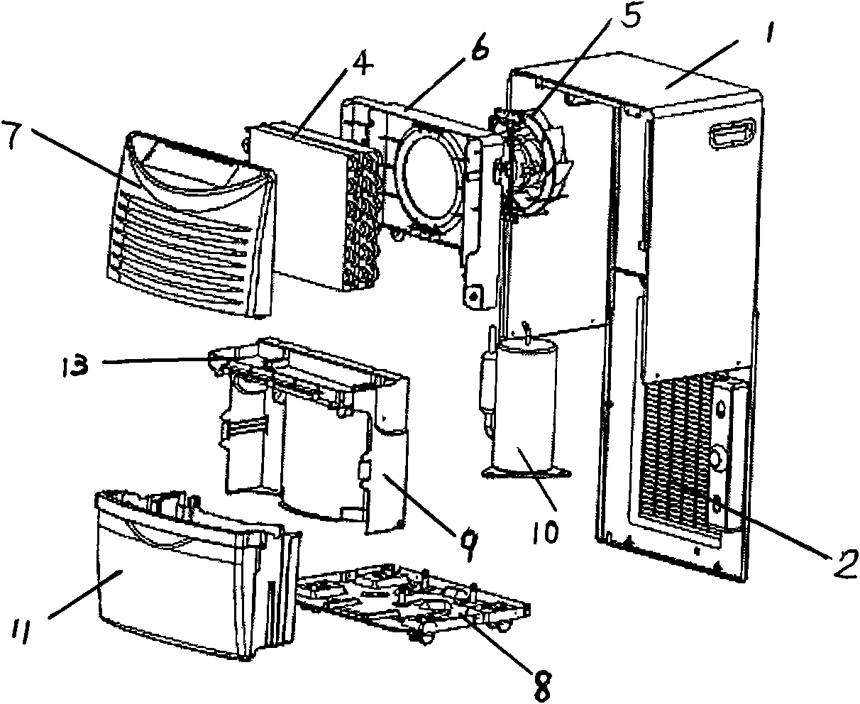
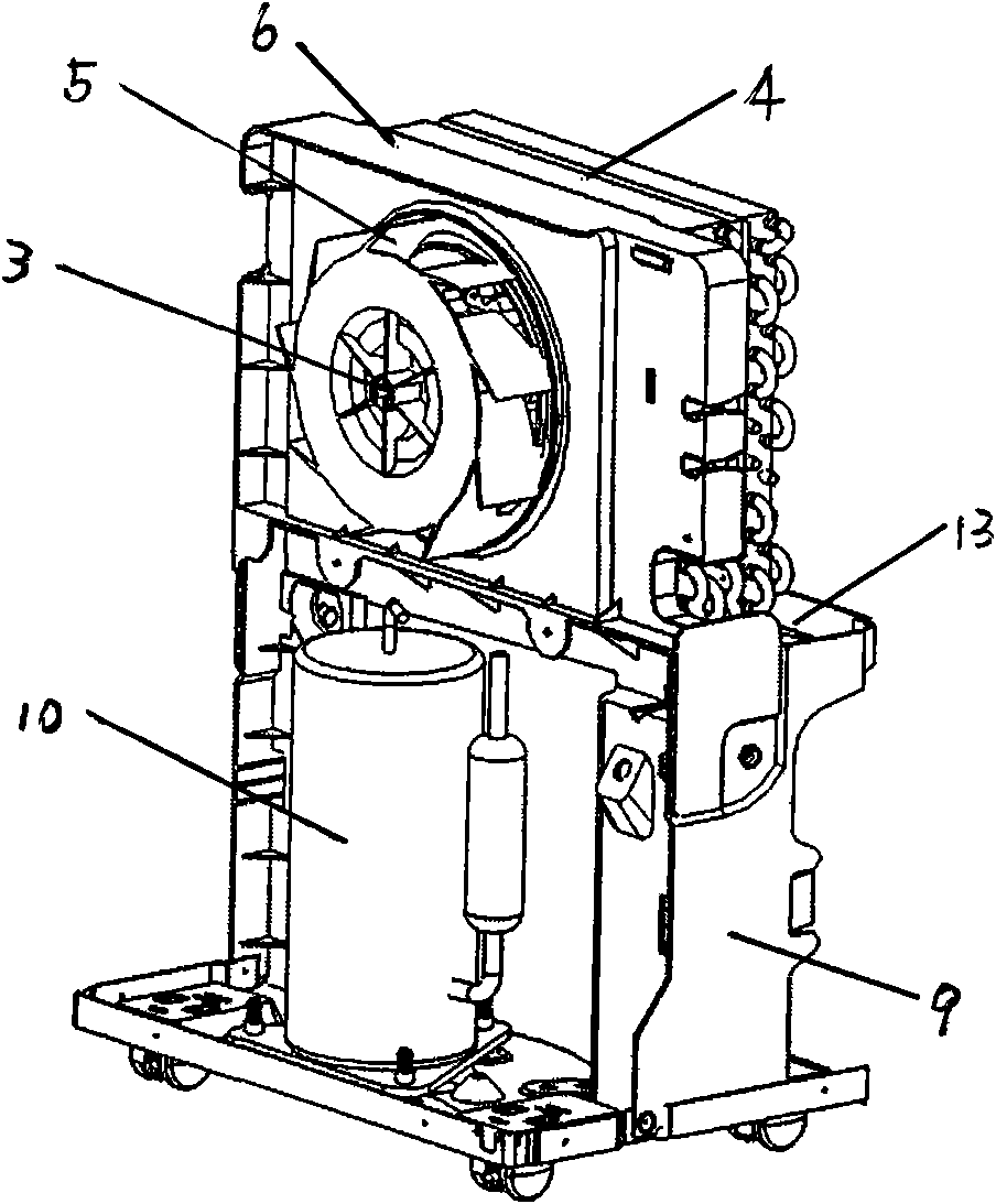
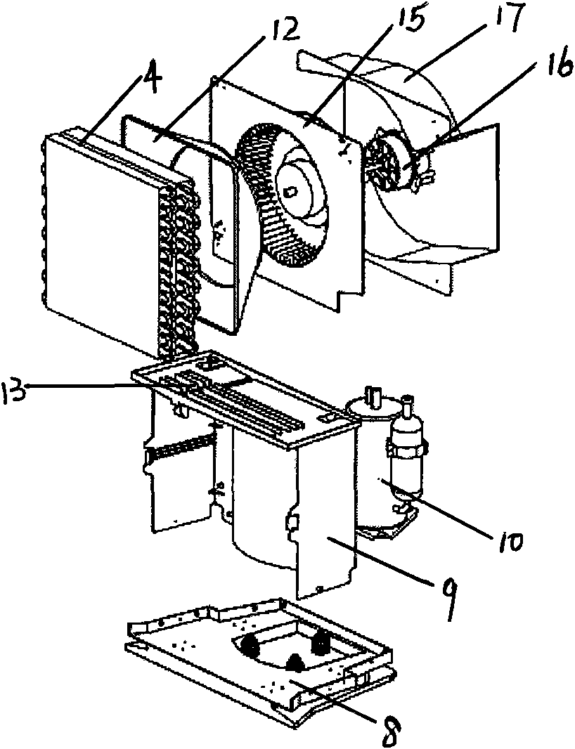
[0017] Such as figure 1 , 3 As shown in 4, the dehumidifier of the present invention includes a casing formed with an air suction port and an air discharge port; a heat exchanger 4 composed of an evaporator and a condenser, a water receiving bucket 11 for storing condensed water, and the indoor air After being sucked into the inside of the casing, the blower fan 15 and the motor 16 are discharged indoors, and the compressor 10 that compresses the refrigerant circulating in the evaporator and condenser is installed on the bottom ...


PUM


Abstract

The invention discloses a dehumidifier comprising a casing, a heat exchanger, a water receiving barrel, a blowing fan, a motor and a compressor, wherein the blowing fan is a multi-blade centrifugal fan, an intake air guide plate is arranged between the blowing fan and the heat exchanger, an output air guide plate is formed between the blowing fan and the casing at the back face, and the motor of the blowing fan is installed in the output air guide plate. An air guide structure is additionally arranged in the dehumidifier, and the motor of the fan is arranged at the back, which increases the air intake area of the heat exchanger, decreases the system resistance, and enables the air quantity to be increased, the distribution of the air speed to be uniform, and the highest speed to be minimum, so that the heat exchange of a condenser can be effectively enhanced.

Description

Technical field [0001] The invention relates to a dehumidifier, in particular to a dehumidifier with low system resistance and uniform wind speed distribution. Background technique [0002] Generally, a dehumidifier is a device that sucks indoor humid air into the housing of the dehumidifier, reduces the humidity through a heat exchanger, and discharges the reduced humidity to the room to reduce indoor humidity. The above heat exchanger is composed of a condenser and an evaporator with a refrigerant inside. [0003] Such as figure 1 , 2 As shown, the prior art dehumidifier includes: a casing 1 that forms the appearance of the left and right sides and the upper surface, and the front, back and bottom surfaces are open; and is composed of an evaporator and a condenser arranged inside the casing 1 for dehumidification The heat exchanger 4; the compressor 10 that compresses the refrigerant circulating in the evaporator and condenser; is installed in front of or behind the heat exchang...

Claims


Application Information

Patent Timeline
Patent Type & Authority Applications(China)
IPC IPC(8): F24F1/02
Inventor 鲍长桥赵永刚
Owner LG ELECTRONICS (TIANJIN) APPLIANCES CO LTD
Why Eureka
Try Eureka