CT or PET-CT system and positioning method for conducting scanning through same

A technology of PET-CT and scanning position, which is applied in computerized tomography scanner, patient positioning for diagnosis, echo tomography, etc. It can solve the problem of radiation of patients with long positioning time, and achieve the effect of reducing health risks

Active Publication Date: 2014-05-07
SHANGHAI UNITED IMAGING HEALTHCARE
View PDF7 Cites 28 Cited by
  • Summary
  • Abstract
  • Description
  • Claims
  • Application Information

AI Technical Summary

Problems solved by technology

[0009] The purpose of the present invention is to solve the problem that the positioning time is long and the patient is exposed to a lot of radiation when the existing CT system or PET-CT system is used for positioning.

Method used


Image

  • CT or PET-CT system and positioning method for conducting scanning through same
  • CT or PET-CT system and positioning method for conducting scanning through same
  • CT or PET-CT system and positioning method for conducting scanning through same

Examples


Embodiment 1

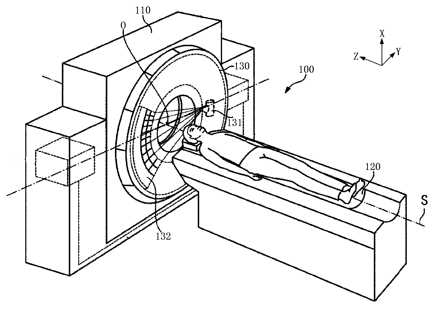
[0054] figure 2 It is a structural schematic diagram of the frame and examination bed in a CT or PET-CT system, such as figure 2 As shown, a CT or PET-CT system 100 includes a gantry 110 having a rotatable portion 130 that rotates about a system axis S (parallel to the Z-axis of the coordinate system) and an examination table 120 . The rotatable part 130 includes an X-ray system with an X-ray source 131 and an X-ray detector 132 . The rotatable part 130 has a center point O which lies on the system axis S and around which the X-ray system can rotate.

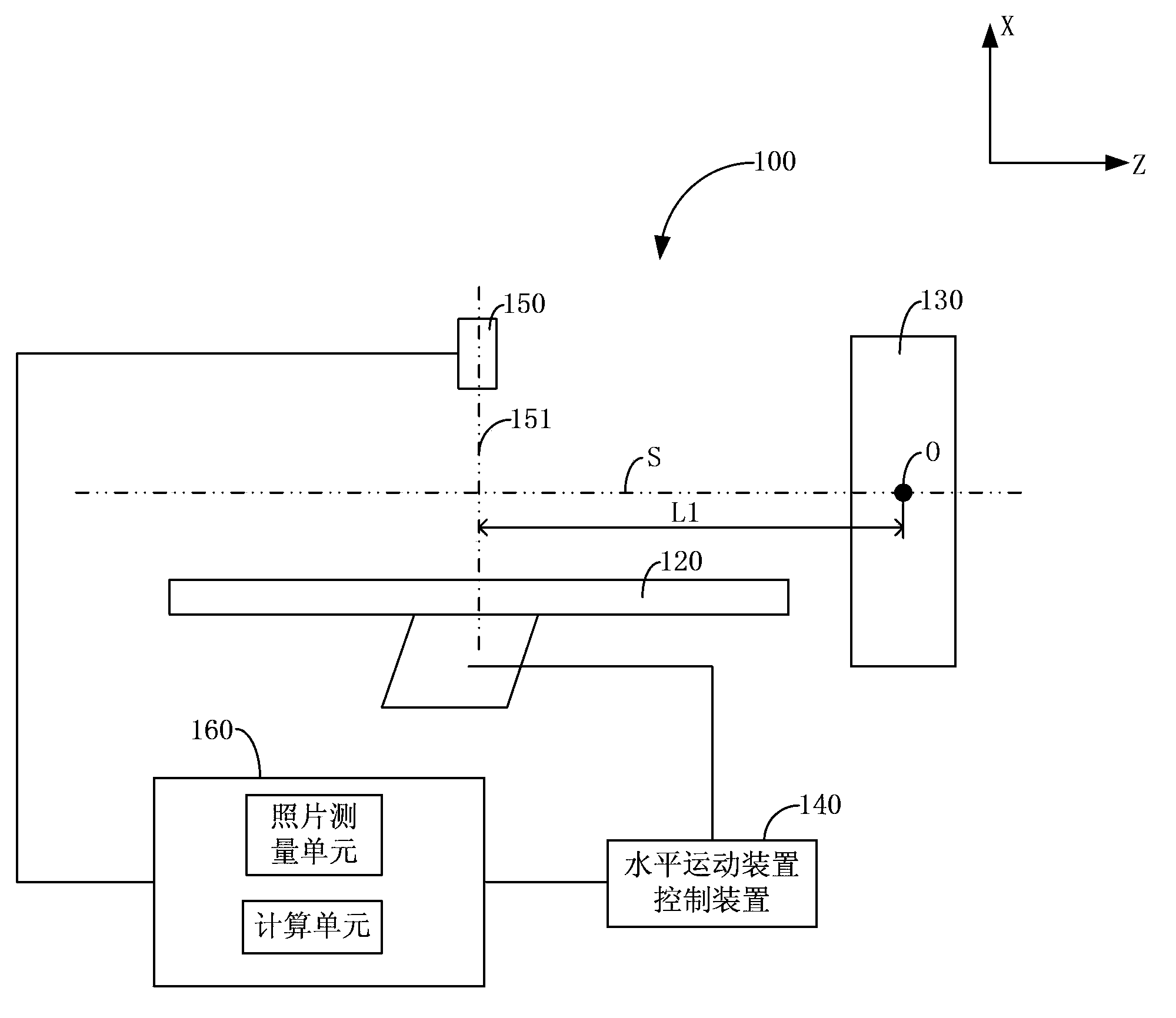
[0055] image 3 It is the front view of the CT or PET-CT system in Embodiment 1 of the present invention (along figure 2 The view projected in the Y-axis direction), Figure 4 It is the left view of the CT or PET-CT system in Embodiment 1 of the present invention (along figure 2 The view obtained by projecting in the Z-axis direction), Figure 5 It is a top view of the CT or PET-CT system in Embodiment 1 of the present...

Embodiment 2

[0085] Figure 7 It is the top view of the CT or PET-CT system in the second embodiment of the present invention (along figure 2 The view obtained by projecting in the X-axis direction), Figure 8 It is the left view of the CT or PET-CT system in the second embodiment of the present invention (along figure 2 The view projected in the Z-axis direction), the Figure 7 , Figure 8 and image 3 , Figure 4 Comparison shows that the difference between the CT or PET-CT system in Embodiment 2 and the CT or PET-CT system in Embodiment 1 is that the reference object 180 is a bump, a groove, or a printed pattern fixedly arranged on the examination table 120, while Not the imaging device lens centerline 151 . As a specific embodiment, the reference object 180 is a rectangular bump, a rectangular groove or a rectangular printing pattern. Of course, the reference object 180 is not limited to the above-mentioned embodiments, as long as the reference object 180 on the electronic pho...


PUM


Abstract

The invention discloses a CT or PET-CT system and a positioning method for conducting scanning through the CT or PET-CT system. The CT or PET-CT system comprises an imaging device and a picture processing device. A patient can not suffer X-ray radiation when positioning is conducted through the CT or PET-CT system, and potential health hazards of the patient are reduced. In addition, in a positioning method for conducting scanning through an existing CT or PET-CT system, an examining table is usually required to move for a quite long time, the examining table scans the patient in the moving process to obtain locating plates, and subsequent examining can be further scheduled only according to the locating plates, and the positioning method mainly includes the steps of obtaining scanning a starting position parameter of the examining table and a scanning stopping position parameter of the examining table. However, by means of the positioning method for conducting scanning through the existing CT or PET-CT system, positioning time is too long. The examining table is kept still when positioning is conducted through the CT or PET-CT system, the scanning starting position of the examining table and the scanning stopping position of the examining table can be known by taking pictures, measuring the electronic pictures and conducting calculation, and positioning time is shortened.

Description

technical field [0001] The present invention relates to computer tomography (Computed Tomography, referred to as CT) technology, in particular to a CT or PET-CT (positron emission tomography-Computed Tomography, positron emission tomography-Computed Tomography) system and a CT or PET-CT system The positioning method to scan. Background technique [0002] Computed tomography uses X-rays to scan specific parts of the human body at a certain thickness. When X-rays are irradiated to human tissues, part of the rays are absorbed by the tissues, and part of the rays pass through the human body and are received by detectors to generate signals. Because the density of various tissues of the human body is different, the penetration ability of X-rays is different, so the rays received by the detector are different. The received different radiation signals are converted into digital information and then processed by the computer to form an image that can be displayed on the fluorescent...

Claims


Application Information

Patent Timeline
Patent Type & Authority Applications(China)
IPC IPC(8): A61B6/03A61B6/04
Inventor 陈牧
Owner SHANGHAI UNITED IMAGING HEALTHCARE
Why Eureka
Try Eureka