Gluing device in medical apparatus mounting equipment

A technology for assembling equipment and gluing devices, which is applied to the device and coating of surface coating liquid, which can solve the problems of uncontrollable gluing amount and low gluing automation, and achieve the effect of improving assembly quality

Active Publication Date: 2014-05-07
MAIDER MEDICAL IND EQUIP
View PDF7 Cites 16 Cited by
  • Summary
  • Abstract
  • Description
  • Claims
  • Application Information

AI Technical Summary

Problems solved by technology

[0005] However, the above-mentioned gluing method still has the problem that the degree of gluing automation is relatively low, and the amount of gluing on the medical device cannot be controlled.

Method used


Image

  • Gluing device in medical apparatus mounting equipment
  • Gluing device in medical apparatus mounting equipment
  • Gluing device in medical apparatus mounting equipment

Examples


Embodiment 1

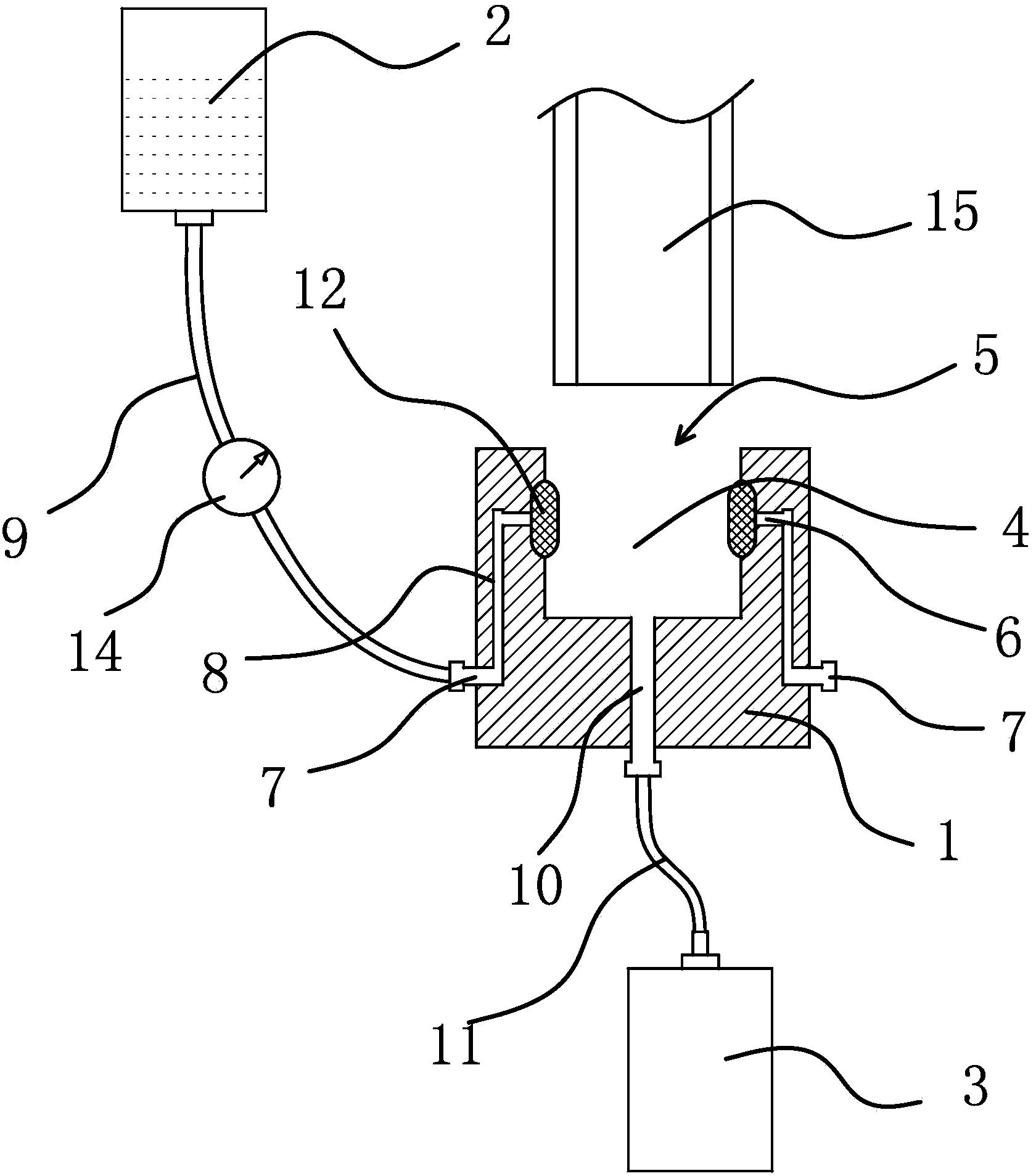
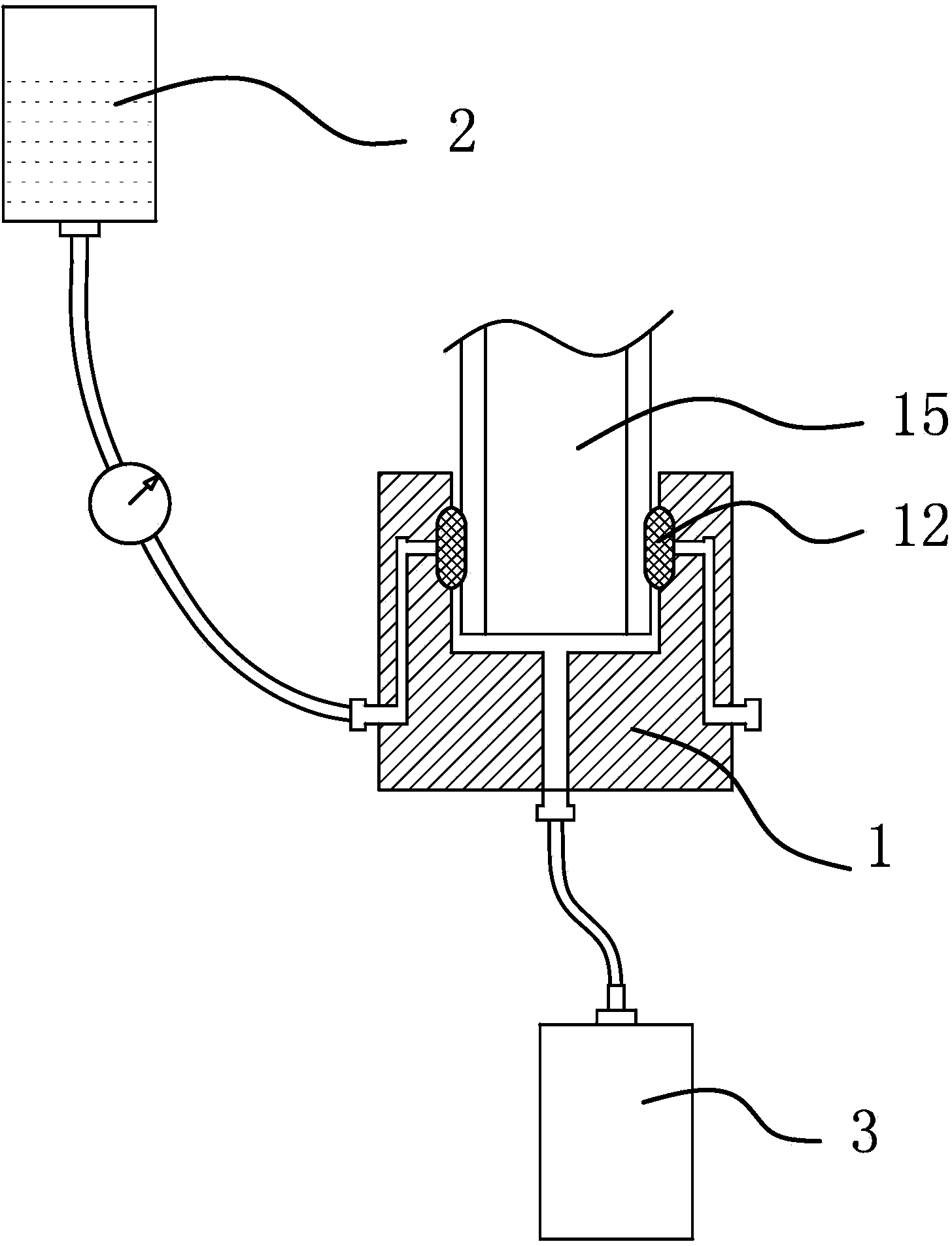
[0022] like figure 1 and figure 2 As shown, the gluing device includes a glue dispensing seat 1, a glue injection barrel 2 and a glue returning barrel 3. The glue dispensing seat 1 is provided with a concave cavity 4, and the concave cavity 4 has an opening 5 that can pass through the target workpiece 15. The concave cavity The inner surface of the 4 is also provided with a glue outlet 6, and the outer surface of the dispensing seat 1 is provided with a glue inlet 7. As a solution, the concave cavity 4 runs through the upper surface of the dispensing seat 1 and forms an opening 5, and the opening 5 is vertical. Straight upward, the inner surface of the concave cavity 4 is fixed with an annular dispensing ring 12, the dispensing ring 12 is made of a glue-absorbing material and can absorb and store glue, the dispensing ring 12 passes through the glue outlet 6, and when dispensing When the ring 12 is in contact with the target workpiece 15 , the glue dispensing ring 12 can coat...

Embodiment 2

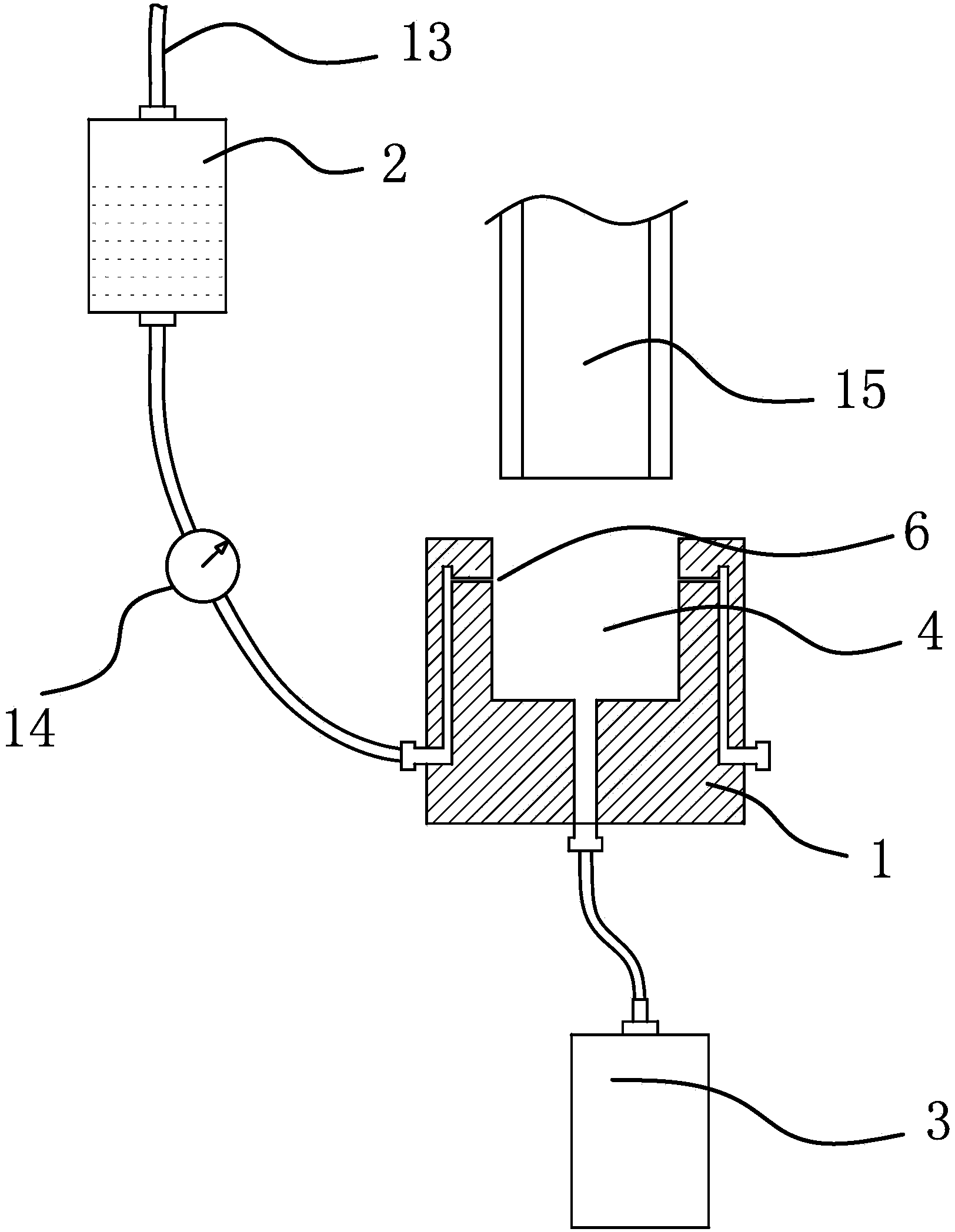
[0026] Such as image 3 and Figure 4 As shown, the general content of this embodiment is the same as that of Embodiment 1, the difference is that in this embodiment, the glue returning channel 10 is arranged along the vertical direction, and the entrance of the glue returning channel 10 is opened on the bottom surface of the concave cavity 4, The outlet of the glue returning channel 10 is set on the bottom surface of the glue dispensing seat 1 , and the glue returning barrel 3 is located under the glue dispensing seat 1 . The vertical setting of the glue returning channel 10 can improve the speed of glue returning, and the location distribution of the outlet and the inlet of the glue returning barrel 3 and the glue returning channel 10 makes the glue returning more thorough. As another solution, the concave cavity 4 runs through the upper end surface of the dispensing seat 1 and forms an opening 5, the opening 5 faces upwards vertically, the glue injection barrel 2 is a clos...


PUM


Abstract

The invention provides a gluing device in medical apparatus mounting equipment, and belongs to the technical field of medical apparatus mounting equipment. The technical problem that the existing gluing device is low in gluing automation degree is solved. The gluing device comprises a dispensing seat, a glue injecting barrel and a glue returning barrel, the dispensing seat is provided with a cavity for providing an opening through which a target work-piece is capable of accessing; the inner side of the cavity is further provided with a glue outlet, the outer side of the dispensing seat is further provided with a glue inlet; the interior of the dispensing seat is provided with a glue inlet channel for communicating the glue outlet and the glue inlet, the bottom of the dispensing seat is provided with a glue returning channel for communicating the cavity and the external; the glue injecting barrel is communicated with the glue inlet through a first connecting pipe, and the glue returning barrel is communicated with the outlet of the glue returning channel through a second connecting pipe. The gluing device provided by the invention is provided with an opening so that the target work-piece can be conveniently inserted, the glue outlet is formed at the side of the cavity so that the adhesion amount of the glue on the target work-piece can be automatically controlled by utilizing the self-weight of the glue, and the precise and constant control can be achieved.

Description

technical field [0001] The invention belongs to the technical field of medical device assembly equipment, and relates to a gluing device in the medical device assembly equipment. Background technique [0002] Medical devices include common medical tools such as disposable infusion sets and disposable syringes. [0003] The current gluing status of medical devices is not ideal. In particular, the assembly and coating of disposable sterile infusion set components is usually done by manual dipping, especially the assembly of medical consumable products such as a drip funnel and a drip funnel cover, a drip funnel cover and a latex cap. Dip the glue in the tank containing the glue, and then assemble the mouth of the drip funnel and the lid of the drip funnel. Because of manual hand-held operation, the amount of glue absorbed by the medical components cannot be accurately grasped. If the glue is too little, it will not stick firmly. And it is easy to cause leakage of the liquid ...

Claims


Application Information

Patent Timeline
Patent Type & Authority Applications(China)
IPC IPC(8): B05C1/06B05C11/105
Inventor 林军华
Owner MAIDER MEDICAL IND EQUIP
Why Eureka
Try Eureka