
Machining device of installation corner connector

A technology for processing equipment and installation corners, which is applied in the field of processing equipment for installation corner codes for curtain walls. It can solve the problems of requiring many personnel, occupying multiple machines, and high costs, so as to achieve high product precision, save operating and production costs, and improve product quality. quality effect

Inactive Publication Date: 2014-05-07
潼南华轩绿色建材有限公司
View PDF5 Cites 5 Cited by
  • Summary
  • Abstract
  • Description
  • Claims
  • Application Information

AI Technical Summary

Problems solved by technology

[0003] The present invention aims at the deficiencies in the background technology, and aims to provide a processing equipment for installing corner codes, which can solve the problems of time-consuming traditional processing and installation of corner codes, taking up multiple machines, requiring many personnel, and high cost. It has the advantages of integration, high efficiency, Time-saving features, and the operation is safe, simple and saves materials

Method used


Image

  • Machining device of installation corner connector
  • Machining device of installation corner connector
  • Machining device of installation corner connector

Examples


Embodiment Construction

[0033] The following will clearly and completely describe the technical solutions in the embodiments of the present invention with reference to the accompanying drawings in the embodiments of the present invention. Obviously, the described embodiments are only some of the embodiments of the present invention, not all of them. Based on the embodiments of the present invention, all other embodiments obtained by persons of ordinary skill in the art without creative efforts fall within the protection scope of the present invention.

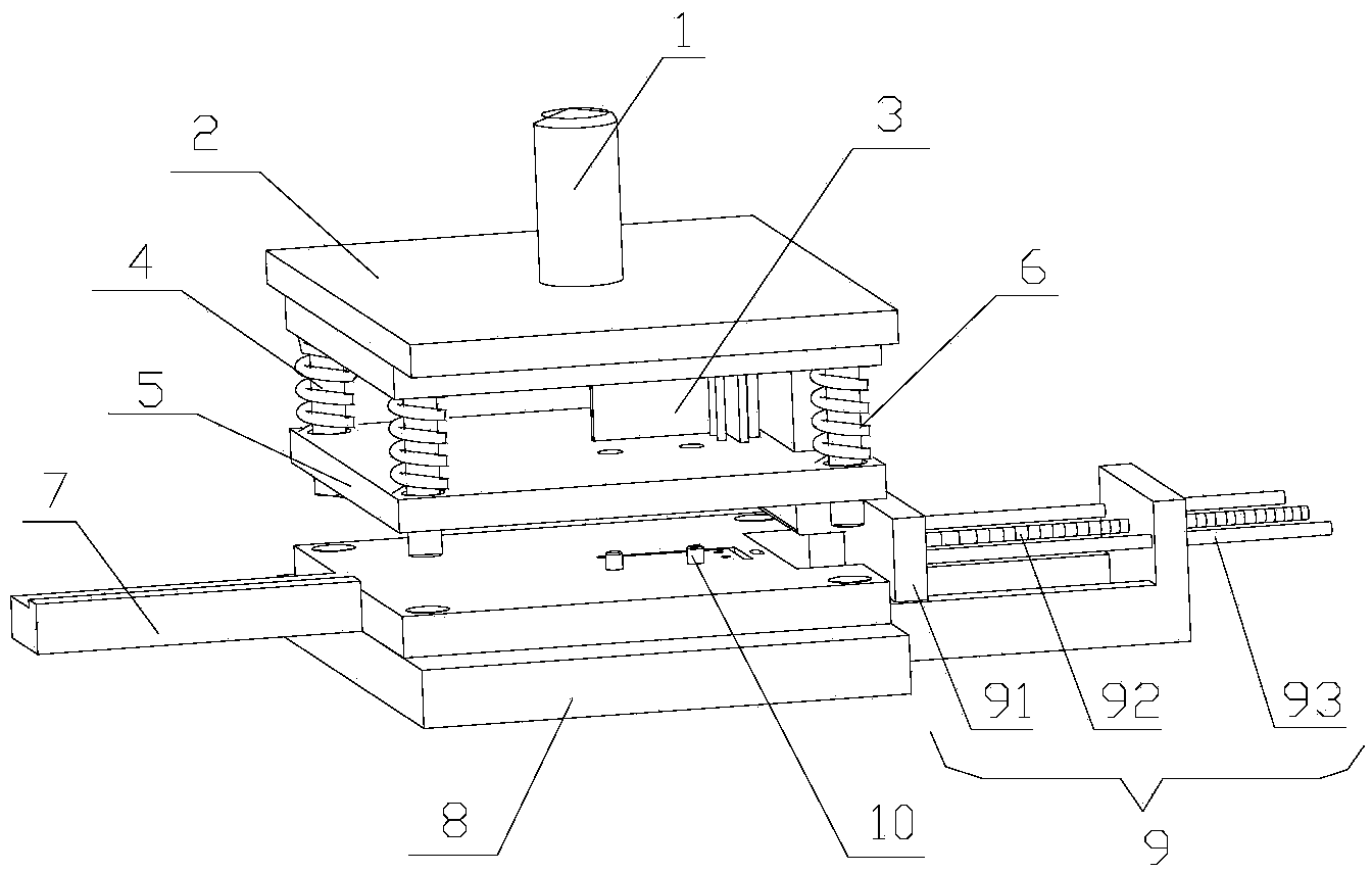
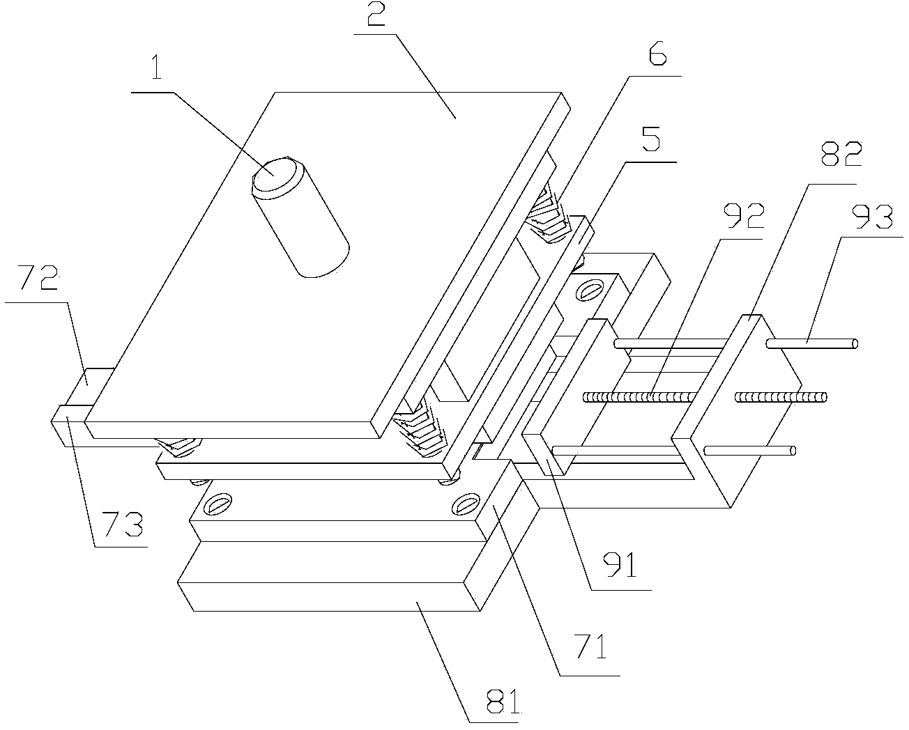
[0034] as attached Figures 1 to 6 As shown, the processing equipment for mounting corner codes is used to process mounting corner codes of different sizes, including an upper mold and a lower mold, and the upper mold includes a mounting handle 1, which is cylindrical and connected to the The upper fixing plate 2 of the installation handle 1, the upper fixing plate 2 is connected to the upper template 3, the upper template 3 is connected to the blanki...


PUM


Abstract

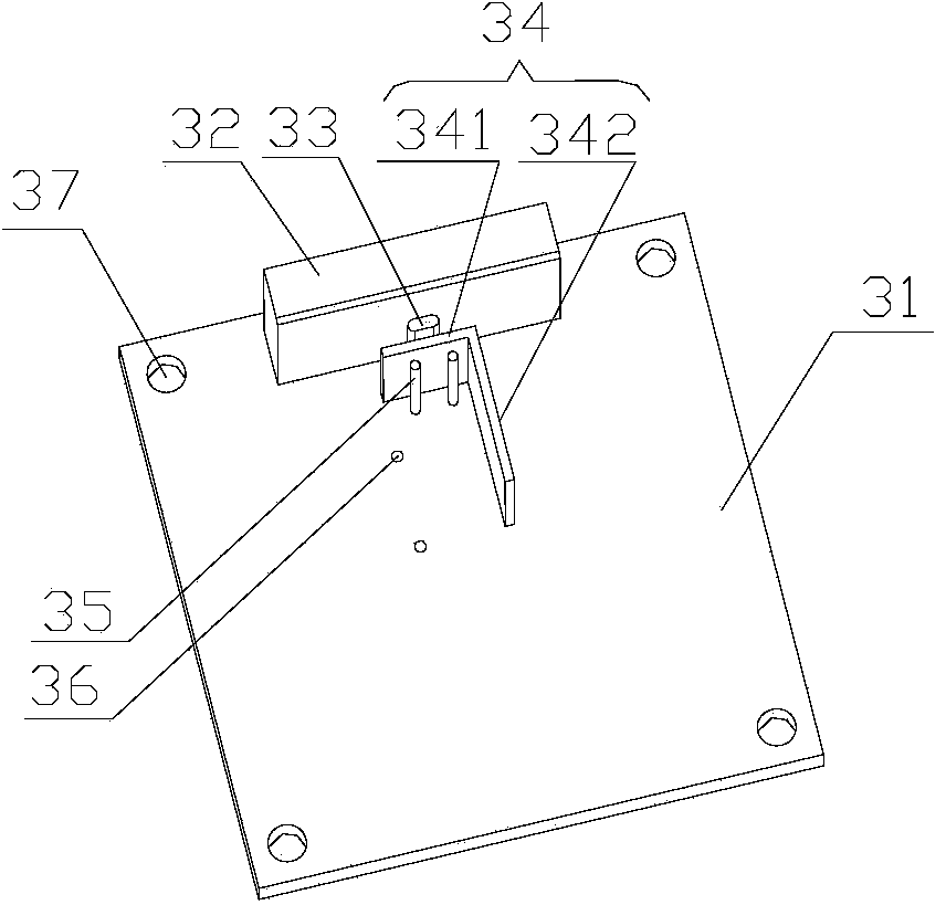
The invention discloses a machining device of an installation corner connector. The machining device comprises an upper mold and a lower mold, wherein the upper mold comprises an installation handle and an upper fixed plate which is connected to the installation handle, the upper fixed plate is connected with an upper mold plate, the upper mold plate is connected with a blanking plate through a guide column, and a spring is sleeved on the guide column; the lower mold comprises a lower mold plate which is matched with the upper mold plate, the lower mold plate is installed on a soleplate, the upper mold plate comprises a plate-like base part, the plate-like base part sequentially vertically extends upwards to form a cutting mold, a kidney-shaped porous mold, a bending mold and two circular hole molds from outside to inside. By designing a composite continuous stamping mold, the cutting mold, the kidney-shaped porous mold, the bending forming mold and the circular hole molds are sequentially distributed on the continuous stamping mold, and the traditional independent four continuous stamping molds are integrated together, so that a product can be continuously machined; the mold is compact and reasonable in design and durable; the consumption of machines, production fields and operation personnel is only two thirds of the traditional equipment, and not only can the product quality be improved, but also the operation and production cost can be saved.

Description

technical field [0001] The invention relates to the technical field of curtain walls, in particular to processing equipment for installing corner codes for curtain walls. Background technique [0002] The processing technology of the traditional installation angle code needs to go through the following steps: the first step is to cut the material and cut out small pieces of raw materials; the second step is to punch out the riveting holes on the upper punching machine; the third step is to punch out the installation waist-shaped holes on the upper punching machine; Four steps, bending and forming on the upper bending machine; the number of machine tools and personnel required for each step is as follows: the first step requires a shearing machine and an operator; the second step requires a punching machine, two A set of molds and two operators; the third step requires a bending machine and an operator. It can be seen that the existing processing steps for installing corner b...

Claims


Application Information

Patent Timeline
Patent Type & Authority Applications(China)
IPC IPC(8): B21D37/10B21D28/14B21D28/34
Inventor 周长生李冬万显锋
Owner 潼南华轩绿色建材有限公司
Learn More