Workbench for vertical milling machine

A technology of vertical milling machine and worktable, which is applied in the direction of manufacturing tools, metal processing equipment, metal processing machinery parts, etc. Blocking, easy to use, working time saving effect

Inactive Publication Date: 2014-05-07
NANTONG GUOSHENG PRECISION MACHINERY
View PDF4 Cites 13 Cited by
  • Summary
  • Abstract
  • Description
  • Claims
  • Application Information

AI Technical Summary

Problems solved by technology

[0002] In industrial production, when the ordinary vertical milling machine is used, a large amount of iron filings will be generated, and these iron filings will accumulate in the T-shaped groove of the worktable, causing the movement of the clamping screw in the slot to be blocked, so that the clamping screw can be put into the It

Method used


Image

  • Workbench for vertical milling machine

Examples


Embodiment Construction

[0011] The preferred technical solutions of the present invention will be described in detail below in conjunction with the accompanying drawings.

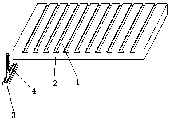
[0012] Such as figure 1 As shown, a workbench for a vertical milling machine of the present invention includes a workbench body 1, on the upper surface of the workbench body 1 there are several parallel inverted "T"-shaped built-in grooves 2, and one is set for the built-in groove 2 The vertical "convex" type latch bar 3 that slides inside is provided with a clamping screw rod 4 for fixing with nuts and bolts of corresponding sizes on the latch bar 3 .

[0013] A bar-shaped groove is arranged on the upper surface of the latch bar 3, the lower end of the clamping screw 4 is placed in the bar-shaped groove, and the clamping screw 4 is slidably connected with the bar-shaped groove.

[0014] The height of the upper surface of the latch bar 3 is lower than the height of the upper surface of the workbench body 1 .

[0015] The latch b...


PUM


Abstract

The invention discloses a workbench for a vertical milling machine. The workbench comprises a workbench body; the upper surface of the workbench body is provided with a plurality of parallel inverted T-shaped built-in grooves; a vertical bolt strip in a shape of a Chinese character 'tu' is arranged and is used for sliding in each built-in groove; the bolt strip is provided with a clamping screw which is matched with a nut and a bolt in corresponding sizes for fixing. Compared with the prior art, the workbench for the vertical milling machine has the advantages that scrap iron in T-shaped grooves on the workbench can be effectively prevented and cleaned, and the position of the screw for fixing in each groove can be convenient to adjust.

Description

technical field [0001] The invention relates to a workbench of a vertical milling machine. Background technique [0002] In industrial production, when the ordinary vertical milling machine is used, a large amount of iron filings will be generated, and these iron filings will accumulate in the T-shaped groove of the worktable, causing the movement of the clamping screw in the slot to be blocked, so that the clamping screw can be put into the It is very troublesome to remove and remove, and there is no suitable tool to clean the T-slot in the usual cleaning, and the previous clamping screw is directly placed in the T-slot, so once the workpiece is clamped, it is inconvenient to carry out Adjustment, this is a common problem in daily production that has not been properly resolved. Contents of the invention [0003] The technical problem to be solved in the present invention is to provide a vertical milling machine workbench structure that is convenient for taking and ...

Claims


Application Information

Patent Timeline
IPC IPC(8): B23Q1/03B23Q3/06
CPCB23Q1/03B23Q3/06
Inventor 姚菊红赵艳秋
Owner NANTONG GUOSHENG PRECISION MACHINERY
Why Eureka
Try Eureka