
A beam type powertrain mount

A powertrain and beam technology, applied in power units, control units, jet propulsion units, etc., can solve problems such as poor vibration isolation performance and occupying space for bodywork, achieve good vibration isolation performance, prolong service life, and optimize decoupling. rate effect

Active Publication Date: 2017-02-08
DONGFENG COMML VEHICLE CO LTD
View PDF7 Cites 0 Cited by
  • Summary
  • Abstract
  • Description
  • Claims
  • Application Information

AI Technical Summary

Problems solved by technology

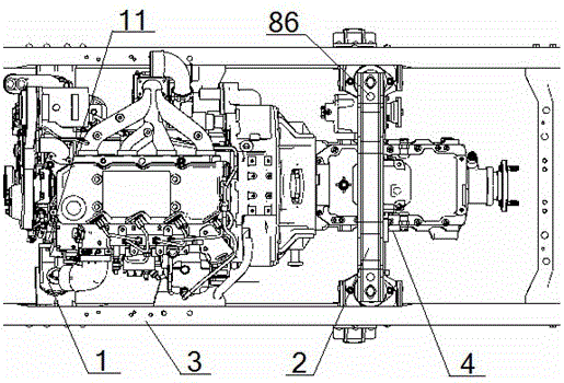
[0007] The purpose of the present invention is to overcome the problems of poor vibration isolation performance and occupation of bodywork space in the prior art, and to provide a beam type powertrain mounting device with good vibration isolation performance and no space occupation for bodywork

Method used


Image

  • A beam type powertrain mount
  • A beam type powertrain mount
  • A beam type powertrain mount

Examples


Embodiment 1

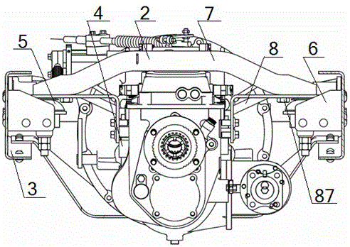
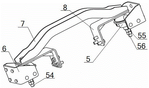
[0054] A beam-type powertrain suspension device, comprising a front suspension 1 and a rear suspension 2, one end of the front suspension 1 is fixedly connected to the engine casing 11, and the other end of the front suspension 1 is connected to the vehicle frame longitudinal beam 3 is fixedly connected, the middle part of the rear suspension 2 is fixedly connected with the gearbox housing side plate 4, and the two ends of the rear suspension 2 are fixedly connected with the frame longitudinal beam 3; the middle part of the rear suspension 2 is connected with the gearbox The middle part of the housing side plate 4 is fixedly connected; the rear suspension 2 includes a mushroom-shaped cushion assembly 5, a rear suspension bracket 6 and a bow-shaped crossbeam 7, and the two ends of the bow-shaped crossbeam 7 are connected to two mushroom-shaped crossbeams respectively. The top of the mushroom-shaped cushion assembly 5 is fixedly connected, the middle part of the mushroom-shaped c...


PUM


Abstract

The invention discloses a cross beam type power assembly suspension device. The cross beam type power assembly suspension device comprises a front suspender and a rear suspender, wherein one end of the front suspender is fixedly connected with an engine shell, the other end of the front suspender is fixedly connected with frame longitudinal beams, two ends of the rear suspender are fixedly connected with the frame longitudinal beams, the middle part of the rear suspender is fixedly connected with the middle part of a gearbox shell side plate, the rear suspender comprises mushroom-shaped cushion assemblies, rear suspender brackets and an arc-shaped cross beam, two ends of the arc-shaped cross beam are respectively and fixedly connected with the top ends of two mushroom-shaped cushion assemblies, the middle parts of the mushroom-shaped cushion assemblies are fixedly connected with the frame longitudinal beams at the same side through the rear suspender brackets, transition connecting supports are arranged between the mushroom-shaped cushion assemblies and the arc-shaped cross beam, and the top parts of the mushroom-shaped cushion assemblies are fixedly connected with the middle part of the gearbox shell side plate through the transition connecting supports. Due to the design, the longitudinal span of a whole vehicle between the front suspender and the rear suspender is increased, the vibration isolation performance is good, and the assembling space is not occupied.

Description

technical field [0001] The invention relates to an automobile power assembly mounting device, in particular to a beam type power assembly mounting device, which is particularly suitable for increasing the longitudinal span of the vehicle between the front and rear mountings and improving the comfort of the vehicle. Background technique [0002] As an important support and vibration isolation element of the powertrain, the engine mount has high requirements for the support and vibration isolation of the engine mount. The existing technology is a four-point mounting method. The engine rear mounting assembly is generally fixed on the engine flywheel housing or the clutch housing. The front and rear mountings have a small longitudinal span of the vehicle and cannot meet the rigidity in a specific direction. and strength requirements, poor vibration isolation performance, and due to more rigid contact, the impact deformation and dynamic deformation of the cushion assembly are rel...

Claims


Application Information

Patent Timeline
Patent Type & Authority Patents(China)
IPC IPC(8): B60K5/12B60K17/06
Inventor 石裕辉王金胜谢浩李海雄
Owner DONGFENG COMML VEHICLE CO LTD
Learn More