A kind of oily wastewater treatment method and equipment

A technology for treating equipment and waste water, applied in water/sewage multi-stage treatment, water/sludge/sewage treatment, chemical instruments and methods, etc., can solve the problem that the removal effect of COD and BOD is not up to standard, the effluent quality is difficult to meet the discharge standard, The emulsification degree of oily wastewater is increased, and the reactor structure is compact, the reactor volume is reduced, and the residence time is shortened.

Inactive Publication Date: 2015-07-29
HOHAI UNIV
View PDF3 Cites 0 Cited by
  • Summary
  • Abstract
  • Description
  • Claims
  • Application Information

AI Technical Summary

Problems solved by technology

The traditional oil-water separation technology relies on gravity and physical filtration. It only has a good treatment effect on floating oil and dispersed oil, but has a poor removal effect on emulsified oil and dissolved oil with small oil particles. Using this technology alone, the treatment The quality of effluent water is difficult to meet the discharge standard
Although ultrafiltration membrane filtration, reverse osmosis and MBR and other membrane treatment systems can effectively remove oil, TOC and salt in wastewater, the emulsification degree of oily wastewater increases, which is likely to cause serious membrane fouling and reduce membrane flux. Membrane regeneration, and the removal effect of COD and BOD is not up to standard, which limits its industrial application

Method used


Image

  • A kind of oily wastewater treatment method and equipment
  • A kind of oily wastewater treatment method and equipment
  • A kind of oily wastewater treatment method and equipment

Examples


Embodiment 1

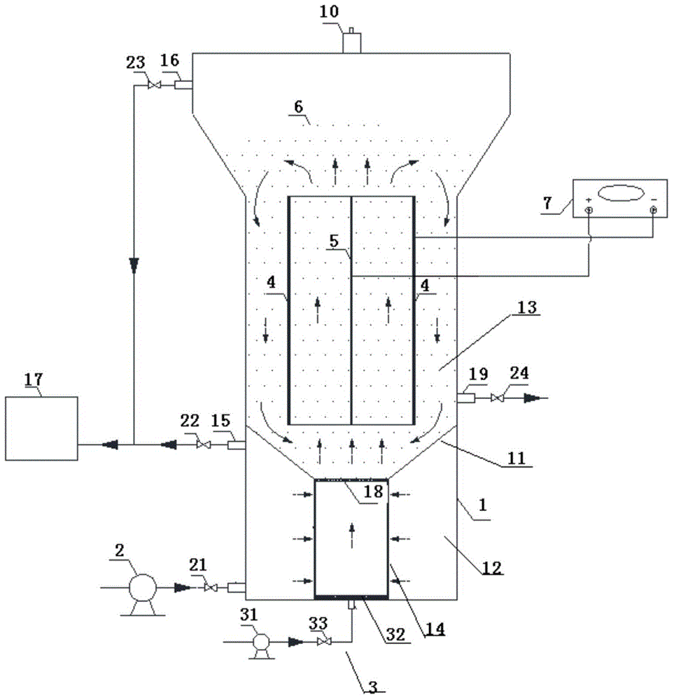
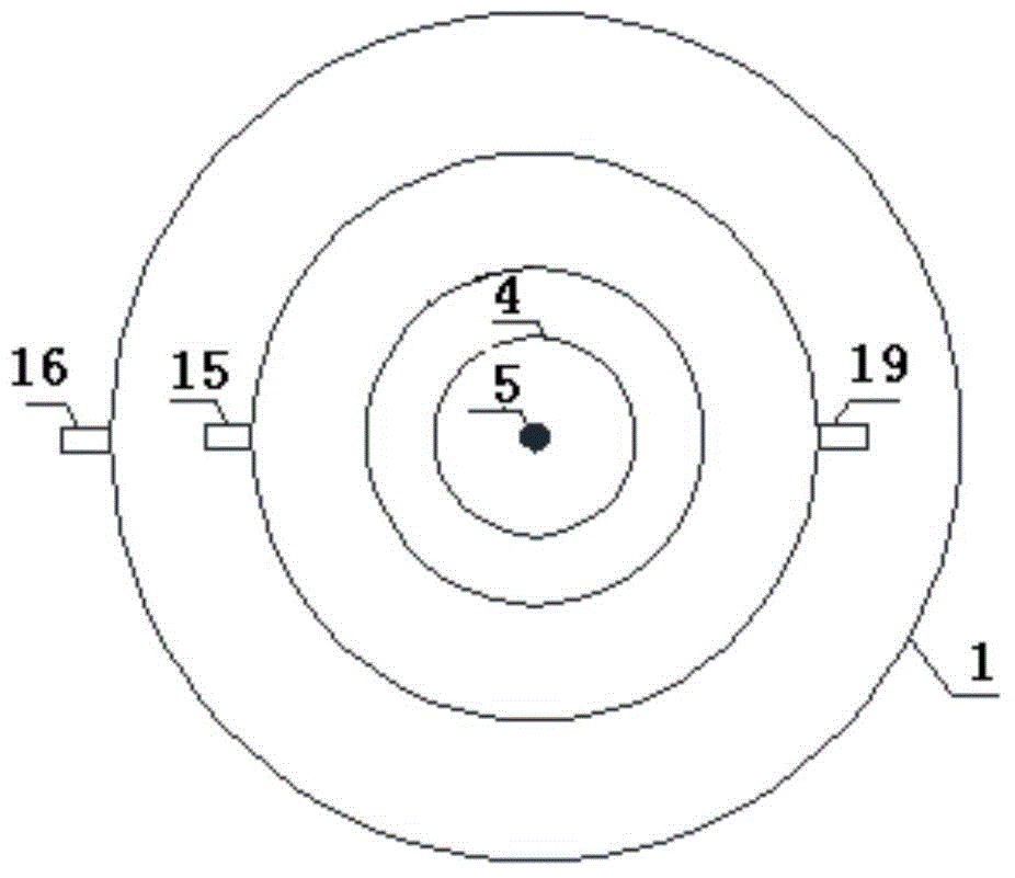
[0033] Treatment equipment for oily wastewater, see figure 1 with 2, comprising a reaction device 1, an inlet pump 2, an aeration device 3, a main anode 4, a main cathode 5, a porous particle electrode 6 and a power supply 7; the reaction device 1 is provided with a partition 11, and the partition 11 will react The device 1 is divided into a lower chamber 12 and an upper chamber 13, the middle part of the partition 11 is a porous support plate 18; the bottom of the lower chamber 12 is connected with the water inlet pump 2, and the top is provided with a No. 1 oil discharge port 15, and the lower chamber The center of 12 is provided with a filter element 14 vertically penetrating through the lower cavity 12; the aeration device 3 includes an air pump 31 and an aeration plate 32 connected in sequence, and the aeration plate 32 is placed at the bottom of the filter element 14; the main anode 4 , the main cathode 5 and the porous particle electrode 6 are all arranged in the upper...

Embodiment 2

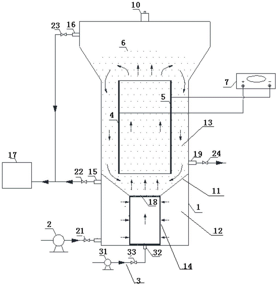
[0038] Treatment equipment for oily wastewater, see image 3 with Figure 4 , basically the same as in Example 1, the difference is that the reaction device 1 is a rectangular structure, the aeration plate 32 and the porous support plate 18, the main anode 4, and the main cathode 5 are all rectangular, and the main anode 4 and the main cathode 5 are placed in parallel , forming the counter electrode.

Embodiment 3

[0040] Treatment equipment for oily wastewater, see Figure 5 , is basically the same as Embodiment 1, and the difference is only: it also includes No. 1 oil monitor 25, No. 2 oil monitor 26, No. 3 oil monitor 27, fine filter screen 28 and automatic control unit 8; The No. 1 oil monitor 25 is arranged on the top of the lower chamber 12, the No. 2 oil monitor 26 is arranged on the top of the upper chamber 13, and the No. 3 oil monitor 27 is connected to the water outlet 19; Described automatic control unit 8 is respectively connected with power supply 7, No. 1 oil content monitor 25, No. 2 oil content monitor 26, No. 3 oil content monitor 27, and described fine filter screen 28 is arranged on the drain port 19, to prevent The porous particle electrodes are lost with the fluid.

[0041] The automatic control unit 8 can set parameters, signal acquisition, analysis, simulation calculation, automatic regulation, error alarm, data recording and other functions according to the need...


PUM

PropertyMeasurementUnit
pore sizeaaaaaaaaaa
particle diameteraaaaaaaaaa

Abstract

The invention provides equipment for processing oily wastewater. The equipment comprises a reaction device, a feed pump, an aerating device, a main anode, a main cathode, a porous particle electrode and a power supply, wherein the reaction device is internally provided with a clapboard, the clapboard divides the reaction device into a lower cavity body and an upper cavity body, a porous support plate is arranged in the middle of the clapboard, the bottom of the lower cavity body is connected with the feed pump, a No.1 oil discharge port is arranged at the top of the lower cavity body, a filter element vertically penetrating through the lower cavity body is arranged in the center of the lower cavity body, the aerating device comprises an air pump and an aerating plate which are sequentially connected, the aerating plate is arranged at the bottom of the filter element, the main anode, the main cathode and the porous particle electrode are all arranged in the upper cavity body, the main anode and the main cathode are connected with the power supply, an exhaust port is arranged at the top of the upper cavity body, a No.2 oil discharge port is arranged at the upper part of the upper cavity body, a drainage port is arranged at the lower part of the upper cavity body, and the No.1 oil discharge port and the No.2 oil discharge port are respectively connected with a reclaimed oil storing device. The equipment has a simple and compact structure, occupies small area, is convenient to run and manage, and has high processing effect and high processing efficiency.

Description

technical field [0001] The invention belongs to the field of water treatment equipment, and in particular relates to an oily waste water treatment equipment, and also relates to a water treatment method using the equipment. Background technique [0002] With the economic growth and the rapid development of industry, oily wastewater pollution has become the focus of environmental problems and has attracted great attention from all walks of life. There are many sources of oily sewage, all of which are oil-water dispersion systems, which can be roughly divided into four types: floating oil, dispersed oil, emulsified oil, and dissolved oil. Its harm is mainly manifested in the serious impact on ecosystems, plants, soil, and water bodies. The discharge of oily wastewater into natural water bodies poses a major threat to the aquatic ecological environment. Oily wastewater can soak into the pores of the soil to form an oil film, resulting in blockage, so that air, water and ferti...

Claims


Application Information

Patent Timeline
Patent Type & Authority Patents(China)
IPC IPC(8): C02F9/08
Inventor 吴东海陆光华林秋红李轶闫振华刘建超
Owner HOHAI UNIV
Why Eureka
Try Eureka