Pneumatic vane motor with rolling pairs

A technology of air motor and rolling pair, which is applied in the direction of rotating or oscillating piston engines, engine components, machines/engines, etc. It can solve the problems of reducing the conversion efficiency of air motors, wear of blades and inner walls of cylinders, etc., and achieves simple structure, small changes, The effect of increasing conversion efficiency

Inactive Publication Date: 2014-05-07
JILIN UNIV
View PDF6 Cites 0 Cited by
  • Summary
  • Abstract
  • Description
  • Claims
  • Application Information

AI Technical Summary

Problems solved by technology

[0003] During the high-speed operation of the vane air motor, the vane and the inner wall of the cylinder will have a large sliding friction, resulting in varying degrees of wear on the vane and the inner wall of the cylinder, reducing the conversion efficiency of the air motor

Method used


Image

  • Pneumatic vane motor with rolling pairs
  • Pneumatic vane motor with rolling pairs
  • Pneumatic vane motor with rolling pairs

Examples


Embodiment Construction

[0016] The preferred embodiments of the present invention will be described in detail below in conjunction with the accompanying drawings, so that the advantages and features of the present invention can be more easily understood by those skilled in the art, so as to define the protection scope of the present invention more clearly.

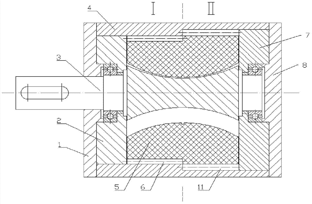
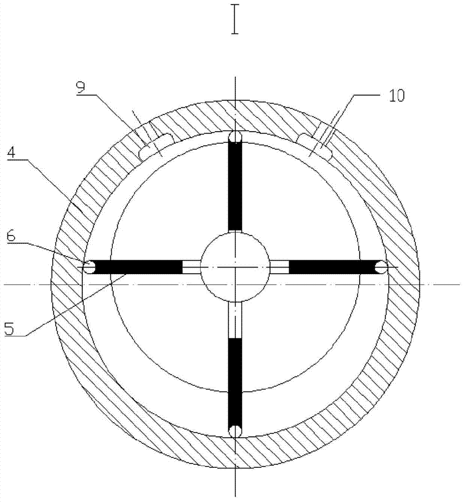
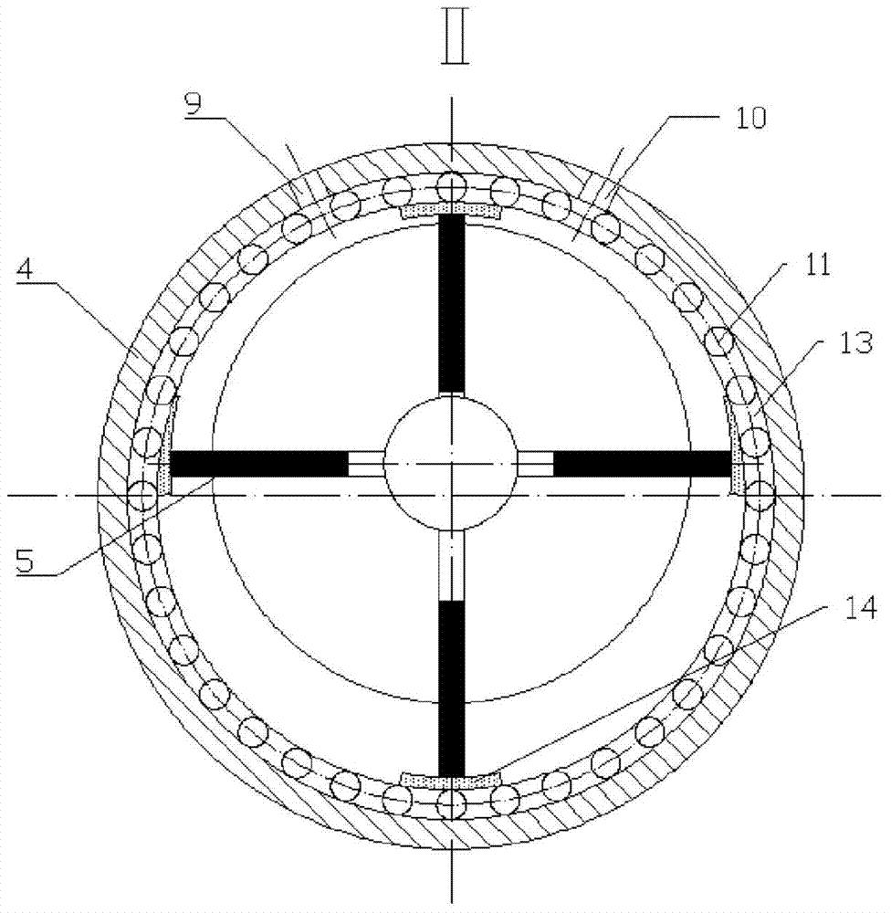
[0017] see figure 1 , figure 2 , image 3 and Figure 4 , the embodiment of the present invention comprises:

[0018] The vane type air motor with rolling pair is mainly composed of front cover 1, rear cover 8, front cover 2, rear end cover 7, rotor 3, cylinder 4, vane 5, air intake hole 9, exhaust hole 10, vane The end rolling pair I and the cylinder inner wall rolling pair II are composed; the cylinder 4 has two air guide holes, one is the air intake hole 9, and the other is the exhaust hole 10. The two air guide holes are symmetrically arranged, and can be connected through the external Change and exchange the functions of the two air gui...


PUM


Abstract

The invention provides a pneumatic vane motor with rolling pairs. The pneumatic vane motor mainly comprises a front machine cover, a rear machine cover, a front end cover, a rear end cover, a rotor, a cylinder, a blade, an intake hole, an exhaust hole, a blade tail end rolling pair I and a cylinder interior wall rolling pair II, wherein the blade tail end rolling pair I and the cylinder interior wall rolling pair II are assembled between the tail end of the blade and the inner wall of the cylinder; the sliding friction between the tail end of the blade and the interior wall of the cylinder is converted into rolling friction by rolling of the blade tail end rolling pair I and the cylinder interior wall rolling pair II. The pneumatic vane motor is simple in structure, and small in change on the original motor; sliding friction between the original blade and the interior wall of the cylinder is converted into rolling friction by common rolling action of the blade tail end rolling pair and the cylinder interior wall rolling pair; abrasion between the blade and the interior wall of the cylinder is effectively reduced; the conversion efficiency of the motor is improved; an auxiliary oil mist spray device and an additional coating are not needed; and the cost is saved.

Description

technical field [0001] The invention belongs to the category of pneumatic motors in the technical field of machinery, and in particular relates to a vane type pneumatic motor with a rolling pair. Background technique [0002] The vane air motor is a prime mover with compressed gaseous working fluid as its power source. It is a device that converts pressure energy into mechanical energy by using the expansion of compressed working fluid. It generally consists of a casing, a machine cover, a cylinder, a rotor, blades, Composed of front and rear end covers, bearings, bushings, thrust rings and other parts, a working chamber is formed between the stator and the rotor. After the compressed working fluid enters the working chamber, the pressure can generate torque on the blades to make the rotor rotate and do work. [0003] During the high-speed operation of the vane air motor, the vane and the inner wall of the cylinder will have a large sliding friction, resulting in varying deg...

Claims


Application Information

Patent Timeline
IPC IPC(8): F01C1/344F01C21/00
Inventor 韩永强康见见柴嘉鸿许允田径刘坤胡智超张文杰姜福仁许闯力
Owner JILIN UNIV
Why Eureka
Try Eureka