A miniature rolling rotor compressor

A rolling rotor and compressor technology, which is applied to machines/engines, liquid fuel engines, rotary piston machines, etc., can solve the problem that the exhaust valve plate and the exhaust hole are not tightly fitted, the deformation recovery ability is weakened, and the compressor is affected. Efficiency and other issues, to achieve the effect of tight fit, reduce exhaust noise, and prevent gas backflow

Active Publication Date: 2016-09-07
高敬雨
View PDF3 Cites 0 Cited by
  • Summary
  • Abstract
  • Description
  • Claims
  • Application Information

AI Technical Summary

Problems solved by technology

However, because the exhaust gas of the compressed cylinder is an intermittent pulse, this causes a relatively large exhaust pressure difference, resulting in noise, which affects the product experience during use
[0005] In addition, after the exhaust valve plate on the exhaust hole has been used for many times, its deformation recovery ability is weakened, which causes the exhaust valve plate and the exhaust hole to not fit tightly, resulting in gas backflow and affecting the efficiency of the compressor

Method used


Image

  • A miniature rolling rotor compressor
  • A miniature rolling rotor compressor
  • A miniature rolling rotor compressor

Examples


Embodiment 1

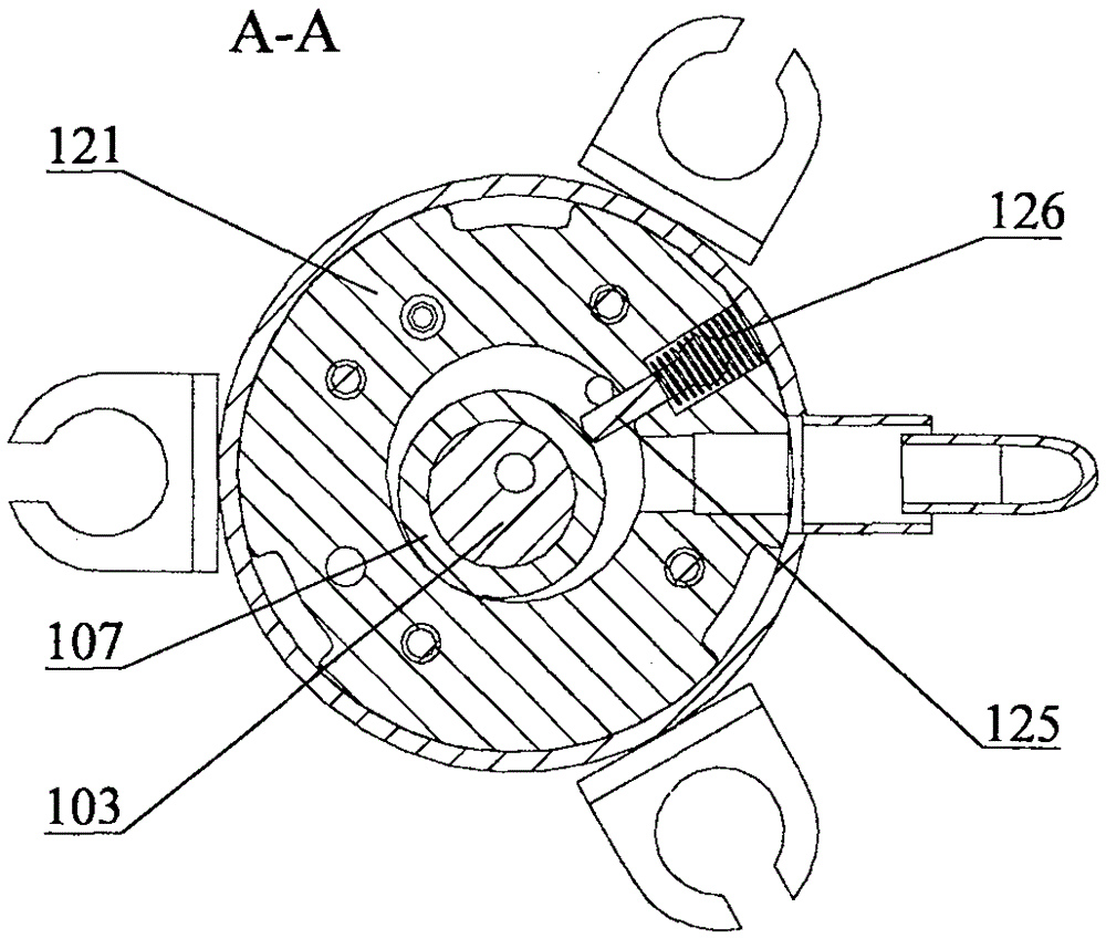
[0026] Such as Figure 1-3 A specific embodiment of a miniature rolling rotor compressor is provided as shown, the compressor includes: a motor 101 and a cylinder; the cylinder includes: a cylinder body 121, an upper flange 105, a cylinder head 130, and an exhaust baffle 111 , the piston 107 sleeved on the rotating shaft 103 and the vane 125, the vane 125 is fixed on the cylinder body 121 by a spring.

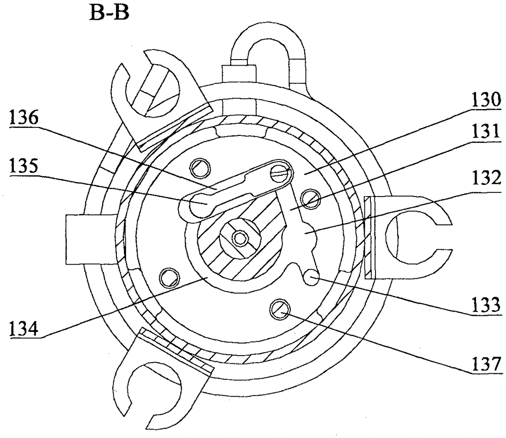
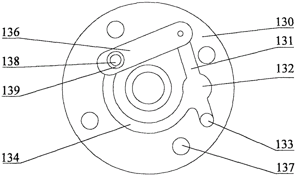
[0027] combine Figure 3-5 As shown, the cylinder head 130 is provided with: a first exhaust hole 133 , a second exhaust hole 138 , an exhaust groove and an exhaust valve plate 135 . Wherein, the exhaust groove is composed of a first exhaust groove 131, a second exhaust groove 134 and an exhaust valve plate installation groove 136, and the second exhaust hole 138 is arranged at one end of the exhaust valve plate installation groove 136 The exhaust valve plate 135 is fixed to the other end of the exhaust valve plate mounting groove 136 by screws, and the exhaust valve plate 13...

Embodiment 2

[0031] Such as Figure 6 As shown, the difference from Embodiment 1 is that in this embodiment, the second exhaust groove 134 is also provided with a sound-absorbing resonant cavity 1322, which can be a semicircular or square structure, and a circular structure Then it has better gas flow, and the cavity communicates with the second exhaust groove 134 . In the compressor, since the discharged gas is pulsating, that is, high pressure and low pressure alternately change, this will cause exhaust noise. However, the present embodiment is provided with a noise-eliminating resonant cavity 1322, which can absorb part of the gas into the cavity when the exhaust pressure is high, and the high-pressure gas stored in the cavity can release a part of the gas when the exhaust pressure is low. division. In this way, due to the gas storage function of the cavity, the high and low pressure difference of the pressure pulsation of the discharged gas is reduced, so that the exhaust noise can b...


PUM


Abstract

The invention discloses a minitype rolling rotor compressor. The minitype rolling rotor compressor comprises a motor and a cylinder, wherein a cylinder head is arranged on the cylinder; a first air outlet, a second air outlet, an air discharge groove, and an air discharge valve block are arranged on the cylinder head; the air discharge groove is communicated with the first air outlet and the second air outlet; the air discharge valve block is arranged at the second air outlet and is used for opening and closing the second air outlet; a flange is arranged at the second air outlet in a surrounding manner to jack up the air discharge valve block; a sound damping resonance cavity used for damping noise is formed in the air discharge groove. The flange is arranged on the cylinder head of the compressor, so that the air discharge valve block is more tightly fitted with the flange, air back flow is prevented, the air discharge efficiency is fully increased, and the useful work of the compressor is increased; moreover, the sound damping resonance cavity is formed in the air discharge groove of the cylinder head, so that pulsation difference of the pressure of the discharged air is reduced, and the noise produced during the air discharging process is reduced.

Description

technical field [0001] The invention relates to the field of heat pump equipment or refrigeration equipment, and more specifically relates to a micro-miniature rolling rotor compressor. Background technique [0002] In the field of heat pump equipment or refrigeration equipment, a refrigeration compressor is often used, and the refrigeration compressor usually drives a compression mechanism through an electric motor to achieve gas compression. [0003] Among them, take a cylinder of a micro-miniature rolling rotor compressor as an example. This compression cylinder includes: a cylinder body, an upper flange, a cylinder head, an exhaust baffle, a piston and blades sleeved on the rotating shaft, and the blades pass through the spring It is fixed on the cylinder block 121 to separate the space in the cylinder, one part is used for exhaust, and the other part is used for compressed gas. [0004] Gas discharge is mainly realized through the cylinder head at the bottom, and two e...

Claims


Application Information

Patent Timeline
Patent Type & Authority Patents(China)
IPC IPC(8): F04C29/06F04C29/00F04C18/356
Inventor 汤清安
Owner 高敬雨
Why Eureka
Try Eureka