A cemented carbide radial bearing body for a screw drilling tool and its production method

A cemented carbide, radial bearing technology, applied in the direction of bearing components, shafts and bearings, mechanical equipment, etc., can solve the problems of increasing wear resistance time, easy deformation of radial bearings, short life, etc., to change the impact strength, The effect of accelerating the cooling rate and reducing the frequency

Active Publication Date: 2015-12-02
DEZHOU UNITED GASOLINEEUM MACHINERY
View PDF5 Cites 0 Cited by
  • Summary
  • Abstract
  • Description
  • Claims
  • Application Information

AI Technical Summary

Problems solved by technology

[0003] The radial bearing body produced by the traditional production method is difficult to meet the requirements of the radial bearing on the screw drilling tool
Therefore, the radial bearing is easily deformed during use, has a short life, and often needs to be replaced, and the replacement of the radial bearing is very complicated and reduces work efficiency.
[0004] The invention patent application with application number 201210332936.5 discloses a cemented carbide radial bearing body and its production process. The problem to be solved is to increase the wear resistance time. The diamond shape and spiral arrangement of cemented carbide greatly increase the complexity of the process; and when the gap becomes smaller, it will affect the bonding effect of cemented carbide and bonding alloy. If applied On screw drilling tools, its wear resistance still cannot meet the requirements

Method used


Image

  • A cemented carbide radial bearing body for a screw drilling tool and its production method
  • A cemented carbide radial bearing body for a screw drilling tool and its production method
  • A cemented carbide radial bearing body for a screw drilling tool and its production method

Examples


Embodiment 1

[0050] Embodiment one: the steps that comprise are as follows:

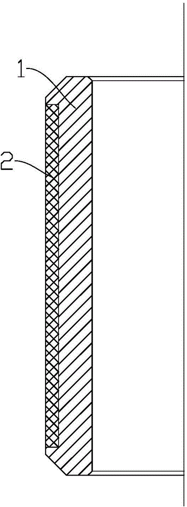
[0051] a) The step of producing the cemented carbide strip 2; when producing the cemented carbide strip 2, the mass ratio of cobalt powder is 8%, and tantalum and / or niobium rare metals with a mass ratio of 0.2% are added; the rest is tungsten powder ;

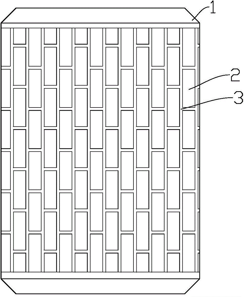
[0052] b) the step of making said inner steel body 1;

[0053] c) Steps for making the bushing 5;

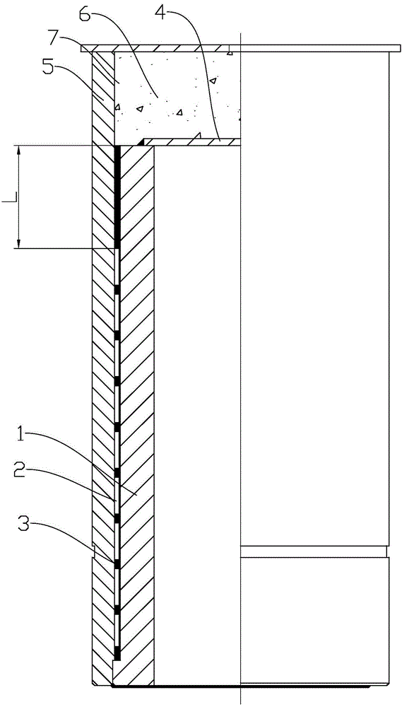
[0054] d) a step of welding the cover plate 4 on the top end of the inner steel body 1;

[0055] e) The step of bonding the cemented carbide strips 2 on the surface of the inner steel body 1; gaps are provided between the cemented carbide strips 2;

[0056] f) The step of loading the inner steel body 1 with the cover plate 4 welded and the cemented carbide strip 2 bonded into the bushing 5;

[0057] The length L between the top surface of the inner steel body 1 and the uppermost cemented carbide strip 2 is 45mm;

[0058] g) the step of filling the gaps between...

Embodiment 2

[0066] Embodiment two: the steps that comprise are as follows:

[0067] a) The step of producing the cemented carbide strip 2; when producing the cemented carbide strip 2, the mass ratio of cobalt powder is 10%, and tantalum and / or niobium rare metals with a mass ratio of 0.3% are added; the rest is tungsten powder ;

[0068] b) the step of making said inner steel body 1;

[0069] c) Steps for making the bushing 5;

[0070] d) a step of welding the cover plate 4 on the top end of the inner steel body 1;

[0071] e) The step of bonding the cemented carbide strips 2 on the surface of the inner steel body 1; gaps are provided between the cemented carbide strips 2;

[0072] f) The step of loading the inner steel body 1 with the cover plate 4 welded and the cemented carbide strip 2 bonded into the bushing 5;

[0073] The length L between the top surface of the inner steel body 1 and the uppermost cemented carbide strip 2 is 50 mm;

[0074] g) The step of filling the gaps betwe...

Embodiment 3

[0082] Embodiment three: the steps that comprise are as follows:

[0083] a) The step of producing the cemented carbide strip 2; when producing the cemented carbide strip 2, the mass ratio of cobalt powder is 8.5%, and tantalum and / or niobium rare metals with a mass ratio of 0.23% are added; the rest is tungsten powder ;The " / " represents the relationship of or;

[0084] b) the step of making said inner steel body 1;

[0085] c) Steps for making the bushing 5;

[0086] d) a step of welding the cover plate 4 on the top end of the inner steel body 1;

[0087] e) The step of bonding the cemented carbide strips 2 on the surface of the inner steel body 1; gaps are provided between the cemented carbide strips 2;

[0088] f) The step of loading the inner steel body 1 with the cover plate 4 welded and the cemented carbide strip 2 bonded into the bushing 5;

[0089] The length L between the top surface of the inner steel body 1 and the uppermost cemented carbide strip 2 is 53mm;

...


PUM

PropertyMeasurementUnit
crystal sizeaaaaaaaaaa
hardnessaaaaaaaaaa

Abstract

The invention discloses a hard alloy transverse bearing body for a spiral drilling rig and a production method thereof. The production method comprises the steps: producing a hard alloy strip from 8-10 percent by weight of cobalt powder, 0.2-0.3 percent by weight of tantalum and / or niobium rare metal and the balance of tungsten powder, wherein the length distance between the upper top surface of the internal steel body and the hard alloy strip at the uppermost end is not less than 45 mm, and a grain particle size of tungsten carbide powder filled in a gap between the hard alloy strips is not more than 1.0 mu m; placing a bonding alloy in a bushing above a cover plate, wherein the bonding alloy comprises the following components in percent by weight: 13-16 percent of Ni, 9-11 percent of Zn, 25-27 percent of Mn and the balance of Cu, and the total amount of impurities is not more than 0.5 percent; simultaneously placing 5-8 g of borax; then heating to 1150 DEG C in a bell type furnace, discharging out form the furnace after insulating for 1.5 h; immediately air-cooling, cooling to 830-860 DEG C within 2 h, then naturally cooling to a room temperature in air; and machining. According to the production method, the impact strength of the bearing body is changed under the condition of no increase of process complexity, and cracks can be prevented.

Description

technical field [0001] The invention relates to the technical field of screw drilling tools, in particular to a cemented carbide radial bearing body for screw drilling tools and a production method thereof. Background technique [0002] At present, screw drilling tools are often used in oil and natural gas drilling. There are two sets of radial bearings in the drive shaft assembly of the screw drilling tool. The radial bearing plays the role of righting. Since the lateral force suffered during the drilling process is relatively large and the direction is complicated, the radial bearing needs to have certain strength and wear resistance. [0003] The radial bearing body produced by the traditional production method is difficult to meet the requirements of the radial bearing on the screw drilling tool. Therefore, the radial bearing is easily deformed during use, has a short life, and often needs to be replaced, and the replacement of the radial bearing is very complicated and...

Claims


Application Information

Patent Timeline
Patent Type & Authority Patents(China)
IPC IPC(8): F16C33/00F16C33/06C22C27/04C22C9/05C22C30/06
Inventor 岳林白广辽霍焕志赵振华王凡
Owner DEZHOU UNITED GASOLINEEUM MACHINERY
Why Eureka
Try Eureka