Combined type dynamic seal transmission assembly

A dynamic sealing and combined technology, which is applied in the direction of engine sealing, transmission parts, engine components, etc., can solve the problems affecting the performance of the transmission shaft, the wear of the skeleton oil seal, and the wear of the transmission shaft, so as to reduce the burden on the oil seal and avoid wear and tear , the effect of increasing the service life

Inactive Publication Date: 2014-05-07
TIANJIN QIXING PRECISION MACHINERY
View PDF0 Cites 7 Cited by
  • Summary
  • Abstract
  • Description
  • Claims
  • Application Information

AI Technical Summary

Problems solved by technology

When the rotating parts run at high speed, it will drive the lubricating oil in the box to splash, which is beneficial to the distribution of lubricating oil and lubricating the friction pair; however, since the power is input or output through the transmission shaft, the problem of dynamic sealing of the lubricating oil in the box is that is the main problem faced by those skilled in the art
[0004] In the prior art, the lubricating oil dynamic seal of the transmission device is generally in the form of a skeleton oil seal, which can achieve a better sealing effect; however, the skeleton oil seal will wear out due to long

Method used


Image

  • Combined type dynamic seal transmission assembly

Examples


Embodiment Construction

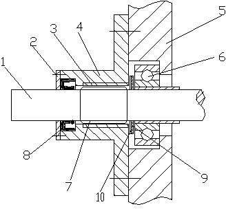
[0019] figure 1 It is a schematic diagram of the structure of the present invention, as shown in the figure: the combined dynamic seal transmission assembly of this embodiment includes a box body 5, a transmission shaft 1 and a shaft seal 8 sleeved on the transmission shaft 1 for sealing the inside and outside of the box body 5 , the transmission shaft 1 is located inside the shaft seal 8 to form a threaded seal shaft section 7, and the box body 5 is formed with a threaded shaft hole 3 that is in clearance fit with the threaded seal shaft section 7, and the thread development direction of the threaded seal shaft section 7 is from inward to The outside is the same as the rotation direction of the transmission shaft 1, and the thread development direction of the threaded shaft hole 3 is the same as the rotation direction of the transmission shaft 1 from the inside to the outside. An oil throwing flywheel 9 is provided, and the outer surface of the oil throwing flywheel 9 is prov...


PUM


Abstract

The invention discloses a combined type dynamic seal transmission assembly. The combined type dynamic seal transmission assembly comprises a case, a transmission shaft and a shaft seal which is sleeved on the transmission shaft to seal the inside and outside of the case. The transmission shaft is arranged inside the shaft seal to form a threaded seal shaft section, the case is provided with a threaded shaft hole which is in clearance fit with the threaded seal shaft section, and the thread extension direction of the threaded seal shaft section and the threaded shaft hole is from inside to outside and is identical to the rotation direction of the transmission shaft. According to the combined type dynamic seal transmission assembly, when the transmission shaft rotates at a high speed, by means of the thrust effect of the threaded seal shaft section and the threaded shaft hole, lubricant oil inside gaps can be pumped back to the case to avoid that large amounts of lubricant oil achieves the oil sealing effects and accordingly to reduce oil seal load; meanwhile, through the centrifugal effect of an oil slinger, neighboring lubricant oil can be thrown onto the outer circumference to facilitate splash lubrication and prolong the service life of bearings; soft oil sealing materials achieve relatively good adaptability and accordingly avoid leakage of lubricant oil due to primary assembling problems. The combined type dynamic seal transmission assembly is applicable to a transmission device with the transmission shaft rotating in one direction.

Description

technical field [0001] The invention relates to a mechanical assembly, in particular to a mechanical device for transmission. Background technique [0002] The transmission device is an intermediate device that transmits the original power to the next device for output, including gearboxes, bearing boxes, etc.; it is an indispensable device for general machinery. For example, the gearbox can reduce the high speed of the engine and electric motor and transmit the output to achieve the purpose of use; of course, there are also transmission devices that realize speed increase, which are manufactured according to practical needs; the bearing box is mainly used to support the drive shaft for transmission. To maintain the stability of the device operation, of course, a certain bearing installation space will also be formed in the gearbox according to needs. [0003] The transmission device generally includes a box body and a transmission shaft, and there are other components such...

Claims


Application Information

Patent Timeline
IPC IPC(8): F16J15/16F16J15/54F16H57/029
Inventor 李洪建
Owner TIANJIN QIXING PRECISION MACHINERY
Why Eureka
Try Eureka