Alignment method of laser alignment device under the control point of theodolite

A technology of laser centering and theodolite, which is applied in theodolite, active optical measuring device, measuring device, etc., can solve the problems of low precision and limited selection of measurement control points, and achieve the effect of improving precision and broad market prospects

Inactive Publication Date: 2016-06-22
孙江
View PDF7 Cites 2 Cited by
  • Summary
  • Abstract
  • Description
  • Claims
  • Application Information

AI Technical Summary

Problems solved by technology

[0004] The purpose of the present invention is to solve the problems of the existing theodolite and the centering of the measurement control point, the low precision and the limited selection mode of the measurement control point, and to provide a method for centering the laser centering device under the control point of the theodolite

Method used


Image

  • Alignment method of laser alignment device under the control point of theodolite
  • Alignment method of laser alignment device under the control point of theodolite
  • Alignment method of laser alignment device under the control point of theodolite

Examples


specific Embodiment approach 1

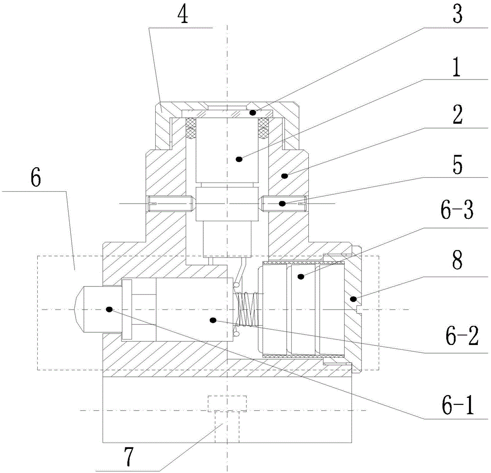
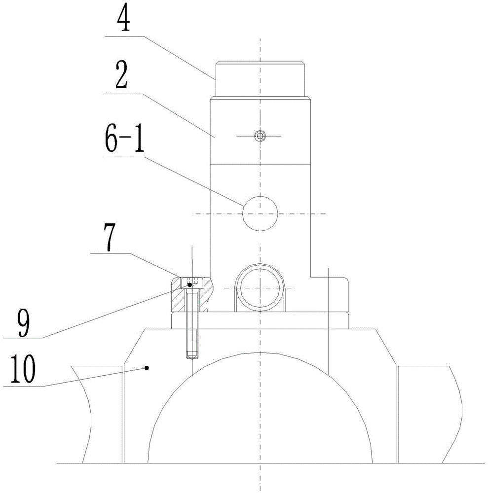
[0028] Specific implementation mode one: the following combination figure 1 and figure 2 Describe the present embodiment, the centering method of the laser centering device under the control point of the theodolite described in the present embodiment, it realizes based on the laser centering device under the control point of the theodolite, and the laser centering device includes a vertical micro-laser 1, Housing 2, laser protection glass 3, glass fixing cover 4, four laser adjustment screws 5, power supply device 6, two positioning through holes 7 and power supply device rear cover 8,

[0029] The shell 2 is divided into a first section and a last section, the first section is cylindrical, and the last section is provided with a cavity along the direction perpendicular to the axis of the first section, and the cavity is connected with the inner cavity of the first section, and the inner cavity of the first section is arranged vertically along the axial direction. Micro lase...

specific Embodiment approach 2

[0035] Specific implementation mode two: the following combination Figure 1 to Figure 3 Describe this implementation mode, this implementation mode will further explain the implementation mode 1, and the step 1 described in this implementation mode is specifically:

[0036] Select a fixed point 1 above the room, set up a theodolite below the fixed point 1, turn on the vertical micro-laser 1 after the telescope of the theodolite is horizontal, and accurately level and align the center of the laser beam spot with the fixed point 1;

[0037] Then turn the theodolite aiming part to observe whether the center of the laser beam spot deviates from the fixed point 1:

[0038] If not, the beam direction of the vertical microlaser 1 coincides with the vertical axis of the theodolite; then perform step 2;

[0039] If so, correct the position of the vertical microlaser 1:

[0040] After rotating the collimator of the theodolite for 180 degrees, determine the center of the laser beam sp...

specific Embodiment approach 3

[0041] Specific implementation mode three: this implementation mode further explains implementation mode two, step two described in this implementation mode is specifically:

[0042] Place the theodolite below the measurement control point; level the telescope of the theodolite, turn on the vertical micro-laser 1; move the legs of the theodolite or turn the foot screw to align the center of the laser beam spot with the measurement control point; extend the legs to adjust the circular level Bubbles; Finally, carry out precise leveling, and translate the theodolite aiming part to align the center of the laser beam spot with the measurement control point.


PUM


Abstract

The invention discloses a centering method of a laser centering device under a control point of a theodolite, belonging to the technical field of control point centering in the use of theodolite. The invention aims at solving the problems that the existing alignment between a theodolite and a measurement control point has low precision and the selection mode of the measurement control point is limited. The method is realized based on a laser centering device under the control point of a theodolite. The laser centering device comprises a vertical micro laser device, a shell, laser protection glass, a glass fixing cover, four laser device adjusting screws, a power supply device, two positioning through holes and a power supply device rear cover; and the centering method comprises the following steps: (I) overlapping the light beam direction of the vertical micro laser device and the vertical axis of the theodolite; and (II) performing laser centering under the control point of the theodolite. The method disclosed by the invention is applied to the centering under the control point of a theodolite.

Description

technical field [0001] The invention relates to a centering method of a laser centering device under a control point of a theodolite, and belongs to the technical field of centering a theodolite in use and a control point. Background technique [0002] In the underground engineering survey of theodolite, in order to avoid the damage of the survey control point, the survey control point is usually selected on the roof of the tunnel or roadway. During the measurement, in order to ensure the centering of the instrument, the vertical ball is hung on the measurement control point on the top plate to be centered with the theodolite. In this way, due to the large cross-section of the roadway, it is not convenient to hang the pendant ball when the roof is high; and the air flow in the roadway is large, the pendant ball will be in a swing state due to the influence of the wind flow, it is not easy to stabilize, and the accuracy of the centering will be affected. Reduced accuracy of ...

Claims


Application Information

Patent Timeline
Patent Type & Authority Patents(China)
IPC IPC(8): G01C25/00G01C1/02
CPCG01C1/02G01C15/004
Inventor 孙江李树奎杜继亮
Owner 孙江
Why Eureka
Try Eureka