Control system for household electrical appliances

A technology for household appliances and control systems, applied in the field of household appliances control systems, can solve the problems of unrealistic, cumbersome power supply line wiring, etc., and achieve the effect of convenient centralized control

Inactive Publication Date: 2014-05-07
THE VANE TECH COMPANY
View PDF8 Cites 10 Cited by
  • Summary
  • Abstract
  • Description
  • Claims
  • Application Information

AI Technical Summary

Problems solved by technology

Although installing the corresponding control module in the power socket can realize the centralized control of the power supply of such household appliances when decorating the wiring and wiring, it is extremely cumbersome or even unrealistic to change the wiring of the power supply line for ordinary households.

Method used


Image

  • Control system for household electrical appliances
  • Control system for household electrical appliances

Examples


Embodiment Construction

[0025] In the following detailed description of the preferred embodiment, reference is made to the accompanying drawings which form a part hereof. The accompanying drawings show, by way of example, specific embodiments in which the invention can be practiced. The illustrated embodiments are not intended to be exhaustive of all embodiments in accordance with the invention. It is to be understood that other embodiments may be utilized and structural or logical changes may be made without departing from the scope of the present invention. Accordingly, the following detailed description is not limiting, and the scope of the invention is defined by the appended claims.

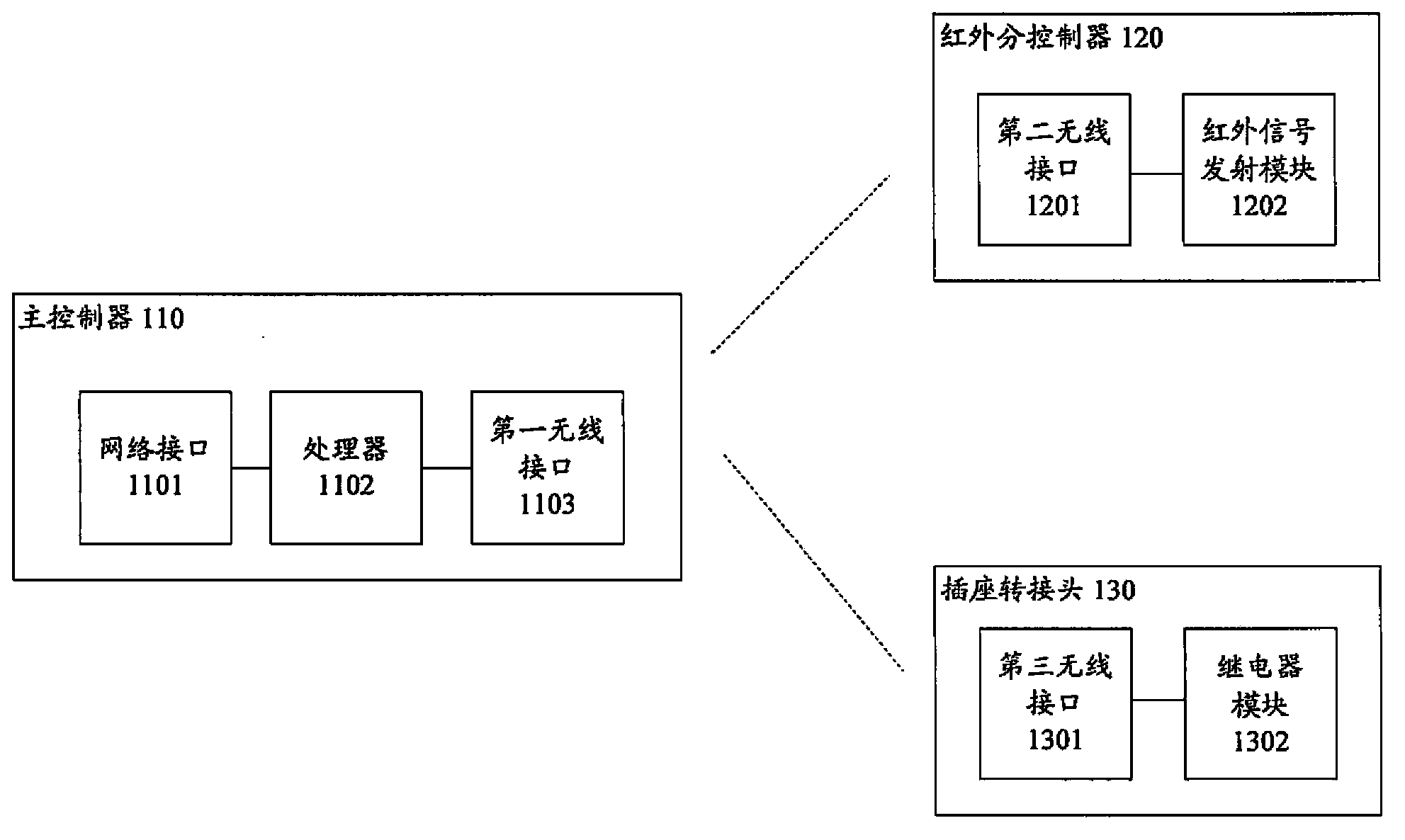
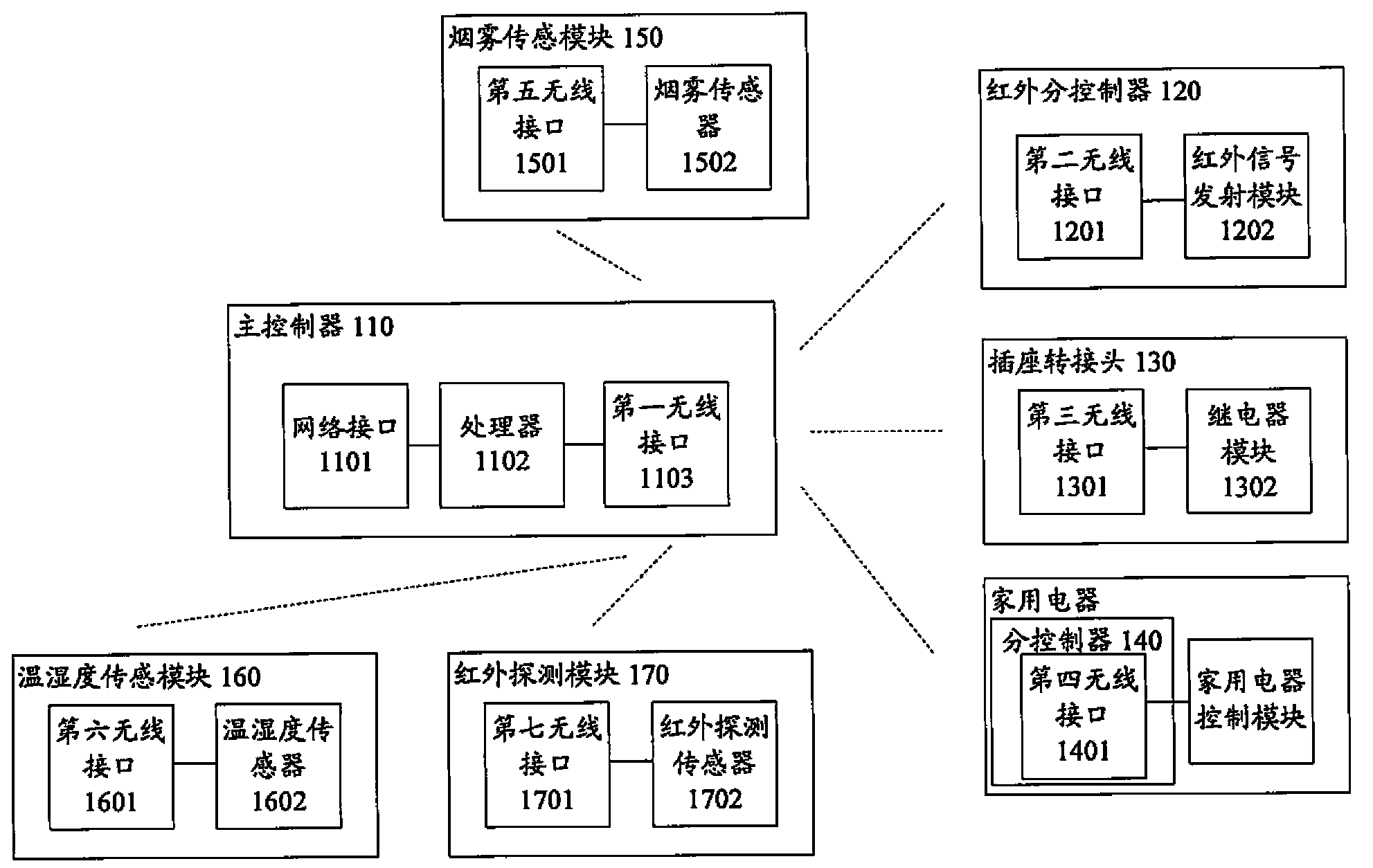
[0026] figure 1 A schematic diagram of a household appliance control system according to an embodiment of the present invention is shown.

[0027] figure 1 The shown home appliance control system includes a main controller 110 , an infrared sub-controller 120 and a socket adapter 130 . Those skilled in the art...


PUM


Abstract

The invention relates to a household appliance control system, comprising a main controller, an infrared auxiliary controller, and a socket adapter. The main controller is provided with a network interface, a processor and a first wireless interface module. The network interface is configured for information interaction with the Internet. The processor is configured to control the first wireless interface module to send wireless signals through information received by the network interface. The infrared auxiliary controller is provided with a second wireless interface module and an infrared signal transmitter module. The second wireless interface module is configured to receive signals from the first wireless interface module, and controls the infrared signal transmitter module to transmit corresponding infrared signals according to the signals. The socket adapter is provided with a third wireless interface module and a relay module. The third wireless interface module is configured to receive signals from the first wireless interface module, and controls disconnection and connection of a relay according to the signals, so that the socket adapter is disconnected or connected. Thus, centralized control of non-intelligent household appliances is easily achieved.

Description

technical field [0001] This patent relates to a household appliance control system. Background technique [0002] With the development of smart home, it has been possible to centrally and automatically control smart household appliances according to predetermined rules. For example, CN 102117062A discloses a smart home system capable of centrally controlling household appliances. [0003] However, in actual use, at present, many household appliances have not integrated modules that support smart home, so it is difficult to introduce smart home systems in ordinary homes. For example, for household appliances without any remote control devices (such as electric water heaters, etc.), if these household appliances need to be centrally controlled, it can only be realized by directly connecting and closing the power supply. Although setting the corresponding control module in the power socket can realize the centralized control of the power supply of this type of household appli...

Claims


Application Information

Patent Timeline
Patent Type & Authority Applications(China)
IPC IPC(8): G05B19/418
Inventor 马延文
Owner THE VANE TECH COMPANY
Why Eureka
Try Eureka