Power-on reset circuit

A technology for resetting the circuit and turning on the power supply, which is applied in the field of circuits and can solve problems such as surges, the inability of the post-stage signal processing system to start operating from the predetermined state, and the reset signal not being sent correctly.

Inactive Publication Date: 2014-05-07
成一电子股份有限公司
View PDF8 Cites 4 Cited by
  • Summary
  • Abstract
  • Description
  • Claims
  • Application Information

AI Technical Summary

Problems solved by technology

[0007] refer to figure 1 and figure 2 , the signal diagram of the power-on reset circuit 1 shows that its shortcoming is: the comparator 13 is constantly comparing the enabling voltage with the reference voltage, so if the enabling voltage starts to rise from the initial time t0, but The reference voltage starts to rise from the first delay time t1 (later than the start time t0), which will cause an unexpected surge in the reset signal from the start time t0 to the first delay time t1
[0008] And this unexpected surge often causes: the reset signal has not been sent correctly, and the post-stage signal processing system (not shown) that receives the reset signal enters the operation mode first
This will cause the post-stage signal processing system to fail to operate from the predetermined state, resulting in unexpected problems

Method used


Image

  • Power-on reset circuit
  • Power-on reset circuit
  • Power-on reset circuit

Examples


Embodiment Construction

[0063] Below in conjunction with accompanying drawing and embodiment the present invention is described in detail:

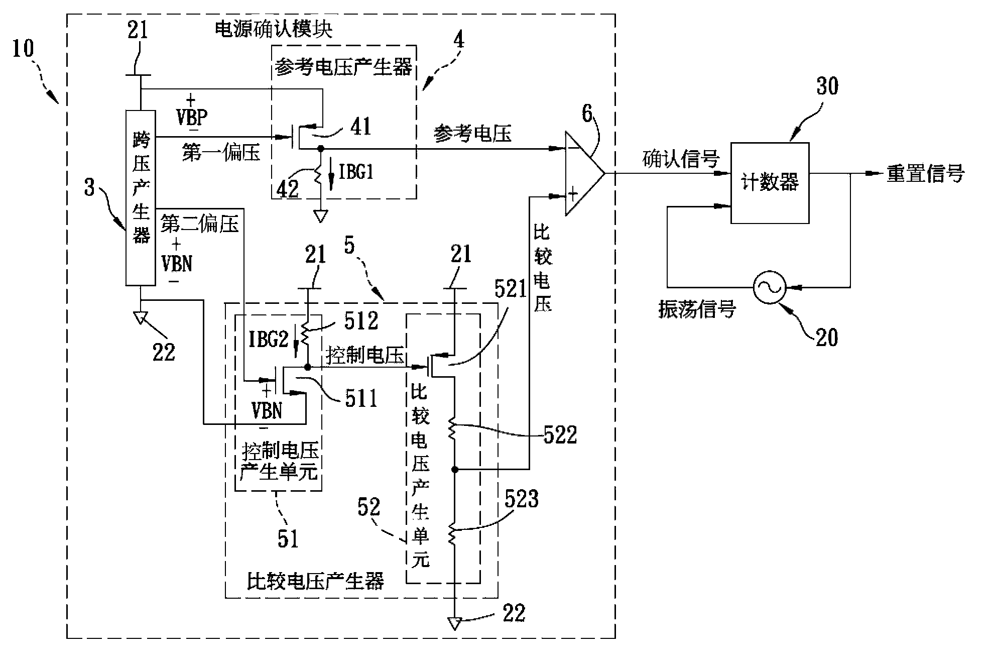
[0064] refer to image 3 , The preferred embodiment of the power-on reset circuit of the present invention includes a power confirmation module 10 , an oscillator 20 and a counter 30 .

[0065] The power confirmation module 10 receives a power supply voltage, and generates a reference voltage and a comparison voltage, and the reference voltage starts to follow the magnitude of the power supply voltage during a first delay time t1, and the comparison voltage changes after a second delay time Time t2 starts to follow the magnitude of the power supply voltage to change, and outputs a confirmation signal according to whether the comparison voltage is greater than the reference voltage, and the second delay time is longer than the first delay time.

[0066] The power confirmation module 10 includes a power terminal 21 , a ground terminal 22 , a cross voltage generat...


PUM


Abstract

A power-on reset circuit includes a power confirmation module and a reset signal generator. The power confirmation module receives a supply voltage and generates a reference voltage and a comparison voltage. A magnitude of the reference voltage rises a first time delay after receipt of the supply voltage, and a magnitude of the comparison voltage rises a second time delay after receipt of the supply voltage. A confirmation signal is outputted based on whether the comparison voltage is greater than the reference voltage or not. The second time delay is greater than the first time delay. The counter is electrically connected to the power confirmation module to receive the confirmation signal and determines whether to start to count or not based on whether the level of the confirmation signal is switched or not so as to generate a counting number. Moreover, the level of an outputted reset signal is switched when the counting number reaches a preset value.

Description

technical field [0001] The invention relates to a circuit, in particular to a power-on reset circuit for initializing an internal circuit after the system is turned on. Background technique [0002] A power on reset (POR) circuit is usually applied in an integrated circuit such as a microcontroller to provide a reset signal for initializing an operation after the integrated circuit is turned on and before operation. [0003] refer to figure 1 , is an existing power-on reset circuit 1 comprising a power voltage divider 11 , a reference voltage generator 12 and a comparator 13 . [0004] The power voltage divider 11 divides a received power voltage Vdd to generate a enable voltage. [0005] The reference voltage generator 12 is used to output a reference voltage. [0006] The comparator 13 is electrically connected to the power voltage divider 11 to receive the enabling voltage, and is electrically connected to the reference voltage generator 12 to receive the reference vol...

Claims


Application Information

Patent Timeline
Patent Type & Authority Applications(China)
IPC IPC(8): G05F1/56
CPCG05F1/56H03L5/00G06F1/24H03K17/223
Inventor 林肇崧
Owner 成一电子股份有限公司
Why Eureka
Try Eureka