Variable-line double-screw rotor structure

A rotor structure and twin-screw technology, applied in the direction of rotary piston pumps, rotary piston machines, rotary piston/swing piston pump components, etc., can solve the problem of the size of the leakage triangle, the difficulty of further improving the efficiency of the screw rotor, and the noise level Can not be further lowered and other problems, to achieve the effect of increased size, compact structure, and low vibration and noise

CN113530819AActive Publication Date: 2021-10-22爱景节能科技(上海)有限公司 +1
8 Cites 0 Cited by

Patent Information

Authority / Receiving Office
CN · China
Patent Type
Applications(China)
Current Assignee / Owner
Publication Date
2021-10-22

Smart Images

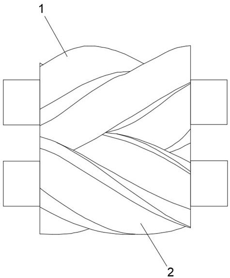
  • Figure 1
    Figure 1
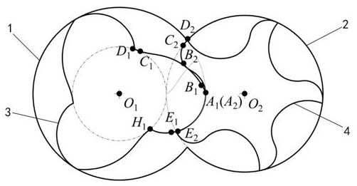
  • Figure 2
    Figure 2
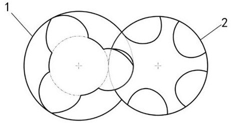
  • Figure 3
    Figure 3
Patent Text Reader

Abstract

The invention provides a variable-line double-screw rotor structure. The variable-line double-screw rotor structure comprises a male rotor and a female rotor, the male rotor is provided with three teeth, the female rotor is provided with five teeth, and a molded line of the male rotor comprises an arc section D1C1, an arc envelope line section C1B1, an arc section B1A1, an arc section A1E1 and a point meshing cycloid section E1H1 which are connected in sequence; a molded line of the female rotor comprises an arc section D2C2, an arc section C2B2, an arc envelope section B2A2 and an arc envelope section A2E2 which are connected in sequence; the radius of the arc section B1A1 is rAB, the radius of the arc section C2B2 is rBC, and the values of the rAB and the rBC are linearly increased along with the increase of the axial position of the rotor from the air suction side to the air exhaust side. The defects in the prior art are overcome, the sizes of leakage triangles on the air suction side and the air exhaust side are reasonably configured by controlling the sizes of the leakage triangles on the air suction side and the air exhaust side of the double-screw rotor structure, the effects of reducing air exhaust pressure pulsation and reducing leakage on the air suction side and the air exhaust side are achieved, the thermodynamic efficiency of the rotor is improved, and the operation noise of the rotors is reduced.
Need to check novelty before this filing date? Find Prior Art

Description

technical field

[0001] The invention relates to the technical field of mechanical design, in particular to a modified double-screw rotor structure. Background technique

[0002] Twin-screw compressor is a volumetric rotary compressor used to obtain low-to-medium pressure gas, and has a wide range of applications in modern industry. It inherits many advantages such as long service life, reliable operation, small vibration, low noise, stable operation, no surge phenomenon, etc. The core component in the supply, refrigeration, waste heat recovery and other systems.

[0003] In the conventional twin-screw compressor rotor structure, the same rotor profile is used at any axial position, which leads to the same leakage triangle at the suction and discharge ends of the rotor. The larger leakage triangle on the exhaust side can effectively form a decompression return channel, reduce exhaust pressure pulsation, and at the same time reduce the length of the meshing line and reduce l...

Examples

Embodiment Construction

[0017] In order to make the purpose, technical solutions and advantages of the present invention clearer, the technical solutions in the present invention will be clearly and completely described below in conjunction with the accompanying drawings in the present invention.

[0018] Such as Figure 1-5 As shown, a modified line twin-screw rotor structure, including a male rotor 1 and a female rotor 2, is characterized in that: the male rotor has 3 teeth, and the female rotor has 5 teeth, and the profile 3 of the male rotor 1 includes the sequence Connected: arc segments D 1 C 1 , arc envelope segment C 1 B 1 , arc segment B 1 A 1 , arc segment A 1 E 1 , point meshing cycloid segment E 1 H 1 ;

[0019] The profile 4 of the female rotor 2 includes sequentially connected: arc segments D 2 C 2 , arc segment C 2 B 2 , arc envelope segment B 2 A 2 , arc envelope segment A 2 E 2 ;

[0020] The arc segment D 1 C 1 is the shaft center of the male...