Boiler energy-saving blowing-out system and method

A boiler and furnace side technology, applied in the field of boiler energy-saving shutdown systems, can solve problems such as environmental thermal pollution, dust collector shutdown, and substandard flue gas emissions, so as to solve environmental thermal pollution, realize waste heat utilization, and solve energy waste. Effect

Pending Publication Date: 2020-11-06
庆元琦丰新能源有限公司
View PDF0 Cites 0 Cited by
  • Summary
  • Abstract
  • Description
  • Claims
  • Application Information

AI Technical Summary

Problems solved by technology

[0005] (1) The operation of the induced draft fan leads to an increase in power consumption
[0006] (2) The air volume of the induced draft fan greatly deviates from the designed air volume after the furnace is shut down, resulting in the stall and surge of the induced draft fan, which seriously affects the life of the fan
[0007] (3) After the furnace is shut down, the dust collector is shut down, and the dust discharged into the atmosphere through the induced draft fan and the chimney seriously exceeds the standard
[0008] (4) The furnace is cooled by induced draft fan, and the cooling air needs to pass through the dust collector, and the resistance of the cooling air is large
[0009] (5) After the boiler is cooled, the temperature of the cooling air is high, and the direct discharge causes waste of heat energy and thermal pollution of the environment
[0010] In summary, after the boiler is shut down, the induced draft fan cools the boiler, there are 1 high power consumption, 2 endangering the safety and life of the induced draft fan, 3 serious problems such as flue gas emission not up to standard, 4 heat energy waste and environmental thermal pollution problems

Method used


Image

  • Boiler energy-saving blowing-out system and method

Examples


Embodiment Construction

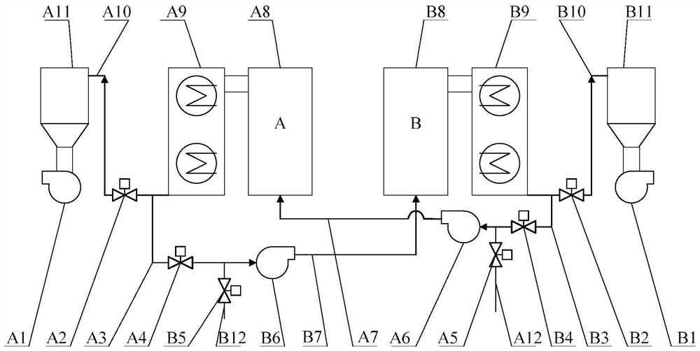
[0032] The present invention will be described in further detail below in conjunction with specific examples, but not as a limitation of the present invention.

[0033] Such as figure 1 As shown, the boiler energy-saving shutdown system of the present invention includes A furnace A8 and B furnace B8, A furnace A8 passes through A furnace air inlet pipe A7 and B furnace bypass flue B3 and B furnace flue gas purification facility inlet flue B10 The air inlet of A furnace A8 is connected to the atmosphere through A furnace air inlet pipe A7, A furnace blower A6 and A furnace blower inlet duct A12, and the A furnace A8 exhaust end is connected to the A furnace tail flue A9 The ends are connected, and the exhaust end of the A furnace tail flue A9 is connected to the A furnace flue gas purification facility through the A furnace flue gas purification facility inlet flue A10, and the A furnace flue gas purification facility A11 is connected to the A furnace induced draft fan A1.

[...


PUM


Abstract

The invention discloses a boiler energy-saving blowing-out system and method. The system comprises a boiler A and a boiler B. Two channels are arranged at an air inlet of an air blower of the boiler A, one channel communicates with an inlet flue of a flue gas cleaning facility of the boiler B through a bypass flue of the boiler B, and the other channel communicates with the atmosphere through an inlet air duct of the air blower of the boiler A. Two channels are arranged at an air inlet of an air blower of the boiler B, one channel communicates with an inlet flue of a flue gas cleaning facilityof the boiler A through a bypass flue of the boiler A, and the other channel communicates with the atmosphere through an inlet air duct of the air blower of the boiler B. When one boiler blows out, discharged flue gas passes through the other boiler, is subjected to dust removal through another boiler operating normally and then is discharged. The problem that flue gas emission does not reach thestandard after blowing-out is solved. After one boiler blows out, an induced draft fan does not operate in a stalling zone of the induced draft fan without surging and harm, the safety is improved, and the service life is prolonged. Hot air going into the boiler blowing out is introduced into the other boiler operating normally for combustion, and utilization of waste heat is realized.

Description

technical field [0001] The invention relates to the field of boilers, in particular to a boiler energy-saving shutdown system and method. Background technique [0002] In the process of China's economic development, the development momentum of energy demand is still rapid. In 2019, China's total industrial added value increased by 5.7% over the previous year, and the added value of industrial enterprises above designated size increased by 5.7%. It decreased by 3.3% in the previous year, but the profits of electric power, heat and other energy production enterprises increased by 15.4% compared with the previous year. [0003] With the increase in demand for electricity and heat, in order to ensure the safety and stability of energy supply, the common practice of most heating stations is: one heating station builds multiple boilers, some of which are in normal operation and the rest are used as backup boilers; After running for a period of time, the standby boiler will be pu...

Claims


Application Information

Patent Timeline
Patent Type & Authority Applications(China)
IPC IPC(8): F23L5/02F23L17/00F23J11/00F23J15/00
CPCF23J11/00F23J15/00F23L5/02F23L17/005
Inventor 钱瑞林张林良李志伟
Owner 庆元琦丰新能源有限公司
Why Eureka
Try Eureka