
Method for determining wind field reactive compensation capacity

A technology for compensating capacity and wind field, which is applied in the direction of reactive power compensation, reactive power adjustment/elimination/compensation, etc., can solve problems such as complicated methods, difficult operation, and difficult to meet the requirements of reactive power compensation capacity configuration, and meet the technical requirements demand, the effect of improving voltage stability

Inactive Publication Date: 2014-05-07
ELECTRIC POWER RESEARCH INSTITUTE, CHINA SOUTHERN POWER GRID CO LTD +2
View PDF3 Cites 11 Cited by
  • Summary
  • Abstract
  • Description
  • Claims
  • Application Information

AI Technical Summary

Problems solved by technology

[0005] The existing methods for determining the reactive power compensation capacity of wind farms do not consider the above problems, and the methods are complicated and difficult to operate, and it is difficult to meet the requirements of reactive power compensation capacity configuration of different types of wind farms and wind turbines today.

Method used


Image

  • Method for determining wind field reactive compensation capacity
  • Method for determining wind field reactive compensation capacity
  • Method for determining wind field reactive compensation capacity

Examples


Embodiment Construction

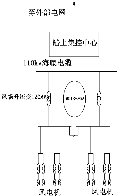
[0033] To figure 1 The typical wind farm shown is taken as an example for description. The typical wind farm is an offshore wind farm, which consists of 66 1.5MW wind turbines. The wind farm collection system is a tree structure with a voltage level of 35kV and a total of 8 collection lines. Back, there are 8-9 wind motors on the collection line every time, connected by submarine cables. There is a sea booster station. The main wiring in the booster station is a single bus section connection. There are 2 transformers with a capacity of 120MVA to boost 35kV to 110kV. The electric energy is transmitted to the land-based centralized control center via a 110kV submarine cable to achieve grid connection.

[0034] Based on the above-mentioned wind farm structure, a method for determining the reactive power compensation capacity of a large-capacity wind farm connected to the regional power grid includes the following steps:

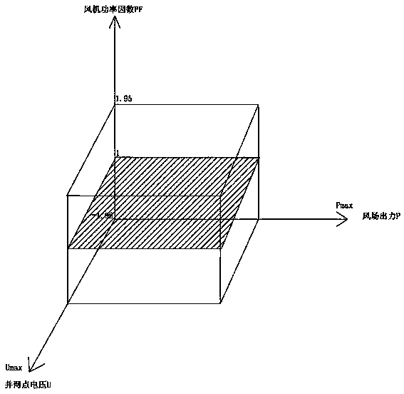
[0035] 1. Such as figure 2 As shown, in the three-dimension...


PUM


Abstract

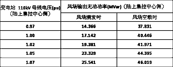
The invention discloses a method for determining wind field reactive compensation capacity. According to the method, three-dimensional space is established with wind field output, wind field grid-connected point voltage and a wind field wind driven generator power factor as coordinate axes, and according to the relations among the wind field output, the wind field grid-connected point voltage, the wind field wind driven generator power factor and wind field output reactive power, the change range of the wind field output reactive power is determined in the three-dimensional space; then according to analysis performed on different types of wind fields and wind driven generator sets, the extreme value of wind field reactive power output is obtained from reactive compensation space so that the wind field output reactive compensation capacity can be determined, and if needed, a reactive compensation device with corresponding capacity is additionally installed in the wind field, so that reactive exchanging between the wind field and a power grid is made to be zero. According to the analysis method of the reactive compensation space, the change range of the wind field reactive power can be accurately obtained, the reactive compensation capacity of the wind field can be rapidly determined, the method can be adaptive to all types of wind fields, reactive compensation performance of the wind field can be fully utilized, and voltage stability of the wind field and the power grid can be improved.

Description

Technical field [0001] The invention relates to the field of power grid optimization analysis, and more specifically, to a method for determining the reactive power compensation capacity of a wind farm connected to a regional power grid. Background technique [0002] Wind power generation is currently one of the most mature technology, the most large-scale development and commercial development prospects for renewable energy power generation. It has been widely used and developed in the past two decades. However, as an intermittent energy source, wind energy is greatly affected by environmental factors such as wind speed. The active power and reactive power of wind farms will change with changes in wind speed. At the same time, the internal circuits of wind farms and transformers are reactive power sources or loads. The output of reactive power in wind farms will cause grid voltage fluctuations, which will affect grid voltage stability and increase regional grid losses. Work com...

Claims


Application Information

Patent Timeline
Patent Type & Authority Applications(China)
IPC IPC(8): H02J3/18
CPCY02E40/30
Inventor 雷金勇陈钢杨振纲陈旭关南强马斌黄焘申展许爱东郭晓斌荆朝霞周少雄杨苹
Owner ELECTRIC POWER RESEARCH INSTITUTE, CHINA SOUTHERN POWER GRID CO LTD
Learn More