
Capacitive welding method and welding device

A welding method and a welding device technology are applied in the field of capacitive welding methods and welding devices, which can solve the problems of damage to the welded object, increase in cost, and difficulty in welding objects, etc., and achieve the effects of preventing surge voltage and simple circuit structure.

Active Publication Date: 2016-01-20
ORIGIN CO LTD
View PDF8 Cites 0 Cited by
  • Summary
  • Abstract
  • Description
  • Claims
  • Application Information

AI Technical Summary

Problems solved by technology

[0005] In this case, there is a problem that if the secondary coils are opened when the wave tail part of the welding current flows through the secondary coils of the welding transformer, a large voltage is induced between the primary coils and at the same time, the welding electrode Sparks called afterflash are generated between the object to be welded, causing damage to the object to be welded
Therefore, it is difficult to obtain high-quality welded items that are not easily scarred by after-flash
In addition, because a discharge switch such as a thyristor with a high withstand voltage must be used, it becomes a cause of cost increase.

Method used


Image

  • Capacitive welding method and welding device
  • Capacitive welding method and welding device
  • Capacitive welding method and welding device

Examples


Embodiment approach 1

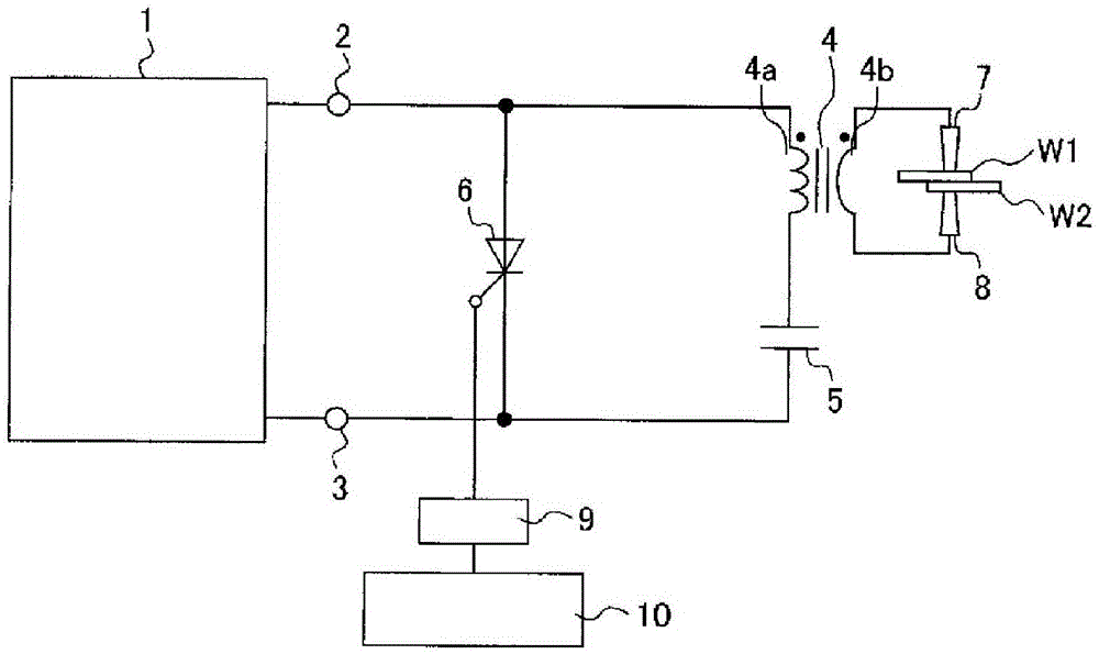
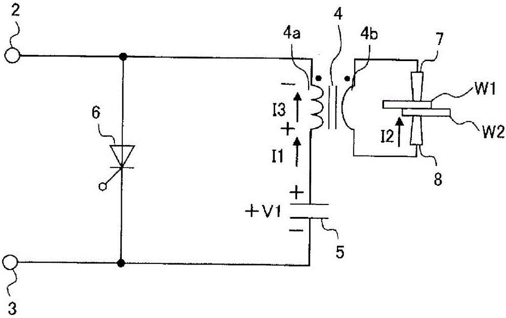
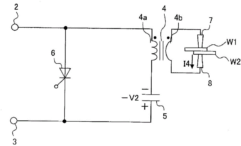
[0035] pass Figure 1 to Figure 6 The welding method and the capacitance type welding device according to Embodiment 1 of the present invention will be described. figure 1 The illustrated capacitive welding device comprises a charging circuit 1, DC output terminals 2 and 3 of the charging circuit 1, a welding transformer 4 having a primary coil 4a and a secondary coil 4b, a capacitor 5 for welding, a switch 6 for discharging, and a secondary The first welding electrode 7 and the second welding electrode 8 connected to the coil 4 b and the controller 10 supply an on signal to the switch 6 for discharge through the insulating drive circuit 9 . In addition, in the description of the first embodiment, reference is made to Figure 1 to Figure 6 .

[0036] W1 and W2 are objects to be welded that are arranged between the first welding electrode 7 and the second welding electrode 8 and that are welded by passing a welding current in a pressurized state. The object to be welded aft...

Embodiment approach 2

[0052] Next, use Figure 7 and Figure 8 A welding method and a capacitance welding device according to Embodiment 2 of the present invention will be described. In Embodiment 2, the welding capacitor 5 is connected in parallel between the DC output terminals 2 and 3 . The series circuit of the primary coil 4 a of the welding transformer 4 and the switch 6 for discharge is connected in parallel to the capacitor 5 for welding. The charging circuit 1 charges the welding capacitor 5 so that the DC output terminal 2 side of the welding capacitor 5 is positive and the DC output terminal 3 side is negative. The charging current supplied from the charging circuit 1 to the welding capacitor 5 does not flow through the primary coil 4 a of the welding transformer 4 . While the charging circuit 1 is charging the capacitor 5 for welding, the switch 6 for discharging is turned off. In addition, in Embodiment 2, the switch 11 for energy recovery connected in parallel with the switch 6 fo...


PUM


Abstract

[Problem] To prevent, with a simple circuit configuration, an after-flash from occurring and a large surge voltage from occurring in a primary winding when opening between welding electrodes between which excitation current is flowing. [Solution] In a capacitor type welding method according to the present invention, electric charges charged on a welding capacitor are discharged and when the discharge current is brought into a state in which the discharge current does not substantially flow through a discharge switch, excitation current that has been flowing through the primary winding of a welding transformer is transferred to the secondary winding thereof. When opening between a first welding electrode and a second welding electrode while the transferred excitation current is flowing through the secondary winding, the discharge switch is brought into a state in which the discharge switch can be turned on by applying a drive signal thereto. Surge voltage occurring in the primary winding of the welding transformer when opening between the first and second welding electrodes is thereby flowed through the discharge switch to the welding capacitor as surge current.

Description

technical field [0001] The present invention relates to a capacitive welding method and welding device for welding a workpiece by discharging energy accumulated in a welding capacitor by a charging circuit in a short time between welding electrodes via a welding transformer. Background technique [0002] Capacitive welding devices take longer than the discharge time to accumulate welding power in the welding capacitor, and discharge it all at once in a short time. Therefore, compared with general alternating-current welding apparatuses, there is an advantage in that it does not increase the capacity of power receiving equipment. There are also advantages in that since the degree of heating of the object to be welded is small, there are almost no welding traces (burn marks) at the welding place, and deformation and the like are also small. Capacitive welding devices are widely used in small to large industrial equipment. [0003] Capacitive welding devices generally use a c...

Claims


Application Information

Patent Timeline
Patent Type & Authority Patents(China)
IPC IPC(8): B23K11/26
CPCB23K11/26
Inventor 角谷康雄新井幸次小松秋男渡边清美
Owner ORIGIN CO LTD
Learn More