A kind of watch hairspring coiling machine

A technology for a coiling machine and a hairspring, applied in the field of coiling machines, can solve the problems of cumbersome operation procedures, low production efficiency, time-consuming and laborious, etc., and achieve the effect of eliminating operation steps, improving production efficiency, and improving rotation accuracy.

Active Publication Date: 2017-04-19
TIANJIN SEAGULL WATCH CO LTD
View PDF5 Cites 0 Cited by
  • Summary
  • Abstract
  • Description
  • Claims
  • Application Information

AI Technical Summary

Problems solved by technology

[0002] The coiling of watch hairspring is an important process in the production of watch hairspring. The coiling machine used is the key equipment for hairspring forming. It largely determines the quality of coiled hairspring, especially the concentricity of the forming mandrel rotation. degree, directly affects the pass rate of the product, and the way of locking the mandrel is the key part that affects the concentricity of the forming mandrel rotation, and the operating structure of the coiling machine equipment also directly affects the production of the product Efficiency, etc., these will have a great impact on the quality of the hairspring and the production efficiency of the product
figure 1 is a schematic diagram of the locking and positioning of the coiled mandrel in the prior art, such as figure 1 As shown, the locking position of the coiled mandrel is locked by the nut, and the elastic groove on the clamp must be locked by the inner tapered surface of the lock nut; Concentricity with the inner cone surface), resulting in uneven force on the cone surface of the clamping nozzle during locking, which directly affects the positioning reference when the clamping nozzle is elastically clamped, resulting in unsatisfactory rotation accuracy of the coil wire mandrel
in addition, figure 2 It is a schematic diagram of the structure of the manual demoulding of the wire coiling machine, such as figure 2 As shown in the figure, every time the hairspring is coiled, it is necessary to manually pull the demoulding handle at the lower part of the coiling machine to remove the material and demould. The operation process is cumbersome, time-consuming and laborious, and the production efficiency is low.

Method used


Image

  • A kind of watch hairspring coiling machine
  • A kind of watch hairspring coiling machine
  • A kind of watch hairspring coiling machine

Examples


Embodiment Construction

[0023] The coil wire machine of the present invention will be described in further detail below in conjunction with accompanying drawing and specific embodiment:

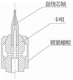
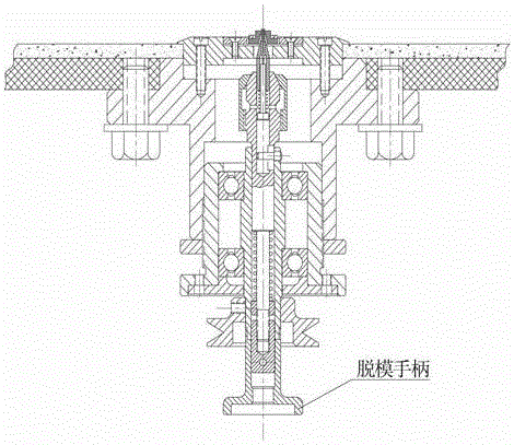
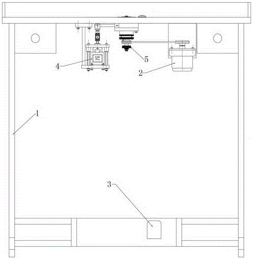
[0024] Such as Figure 3 to Figure 6 As shown, the watch hairspring winding machine of the present invention includes a driving motor 2, a driving control switch 3, an electromagnetic control assembly 4 and a coiling head 5; the driving motor 2 is hoisted and fixed on the back of the workbench of the body platform 1; The foot-operated drive control switch 3 is fixed on the pedal between the two horizontal bars at the bottom of the body platform 1, and the drive motor is controlled by the foot-operated drive control switch 3 to rotate; the electromagnetic control assembly 4 is fixed on On the fixed plate 11 at the back of the workbench of the body platform 1, the electromagnetic control assembly 4 includes an electromagnet group 41, an adjustment lock bar 42 and a linkage lever 43; one end of the adjustment lock leve...


PUM


Abstract

The invention discloses a coiling machine for balance springs of watches. The coiling machine comprises a driving motor, a driving control switch, an electromagnetic control assembly and a coiling machine head. The driving motor is suspended on a machine body platform, and the electromagnetic control assembly is fixed onto the bottom surface of a fixing plate; a belt pulley on a motor shaft of the driving motor drives a belt pulley of the coiling machine head; a linkage lever of the electromagnetic control assembly pushes a mold releasing base to move upwardly. The coiling machine has the advantages that a draw bar type locking positioning mode is adopted, accordingly, interference between locking force of a positioning conical surface of a clamp nozzle and locking force of a draw bar can be prevented, a coiling mandrel positioning reference can be guaranteed, and the coiling mandrel rotation precision can be improved; troublesome operation steps can be omitted owing to an electromagnetic mold releasing mode, accordingly, the labor intensity of operators can be reduced, and the production efficiency can be effectively improved.

Description

technical field [0001] The invention relates to a wire coiling machine, in particular to a wire coiling machine for processing watch hairsprings for coiling and forming. Background technique [0002] The coiling of watch hairspring is an important process in the production of watch hairspring. The coiling machine used is the key equipment for hairspring forming. It largely determines the quality of coiled hairspring, especially the concentricity of the forming mandrel rotation. degree, directly affects the pass rate of the product, and the way of locking the mandrel is the key part that affects the concentricity of the forming mandrel rotation, and the operating structure of the coiling machine equipment also directly affects the production of the product Efficiency, etc., these will have a great impact on the quality of the hairspring and the production efficiency of the product. figure 1 is a schematic diagram of the locking and positioning of the coiled mandrel in the pr...

Claims


Application Information

Patent Timeline
Patent Type & Authority Patents(China)
IPC IPC(8): B21F3/08
Inventor 杜庆鸣荣桂林
Owner TIANJIN SEAGULL WATCH CO LTD
Why Eureka
Try Eureka