Retractable chuck

A telescopic and chuck technology, applied in chucks and other directions, can solve the problems of waste of materials and labor, waste of time, loss of part accuracy, etc., and achieve the effects of shortening processing time, improving accuracy retention, and reducing waste

Active Publication Date: 2014-05-14
山东济清科技服务有限公司
View PDF7 Cites 13 Cited by
  • Summary
  • Abstract
  • Description
  • Claims
  • Application Information

AI Technical Summary

Problems solved by technology

Both of these two processing techniques have disadvantages: the former consumes materials and labor; the latter wastes time and loses the accuracy of parts

Method used


Image

  • Retractable chuck
  • Retractable chuck
  • Retractable chuck

Examples


Embodiment Construction

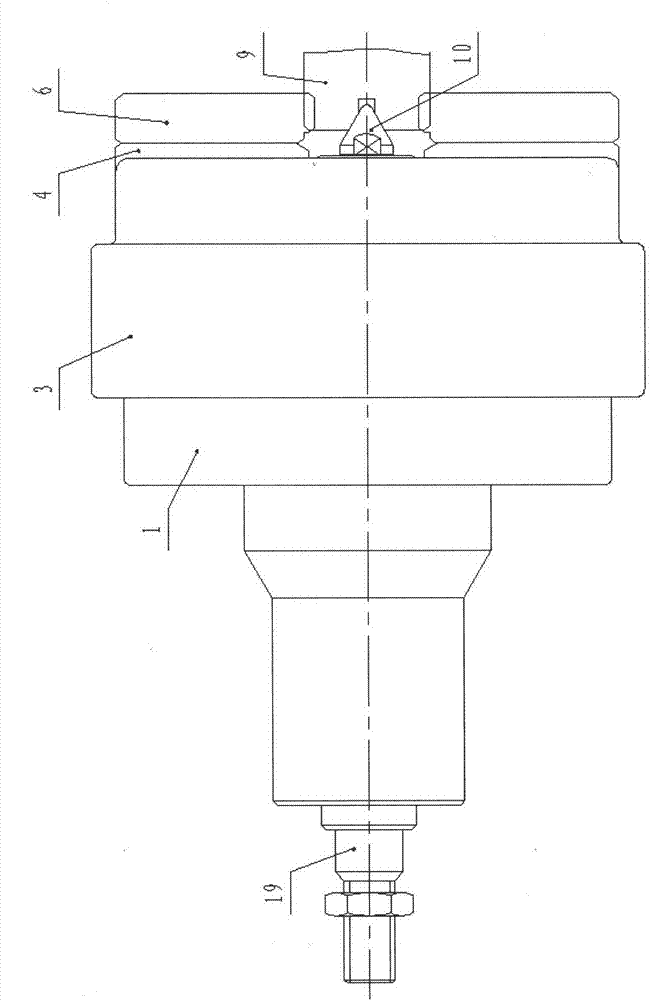
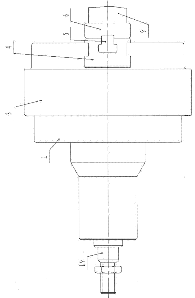
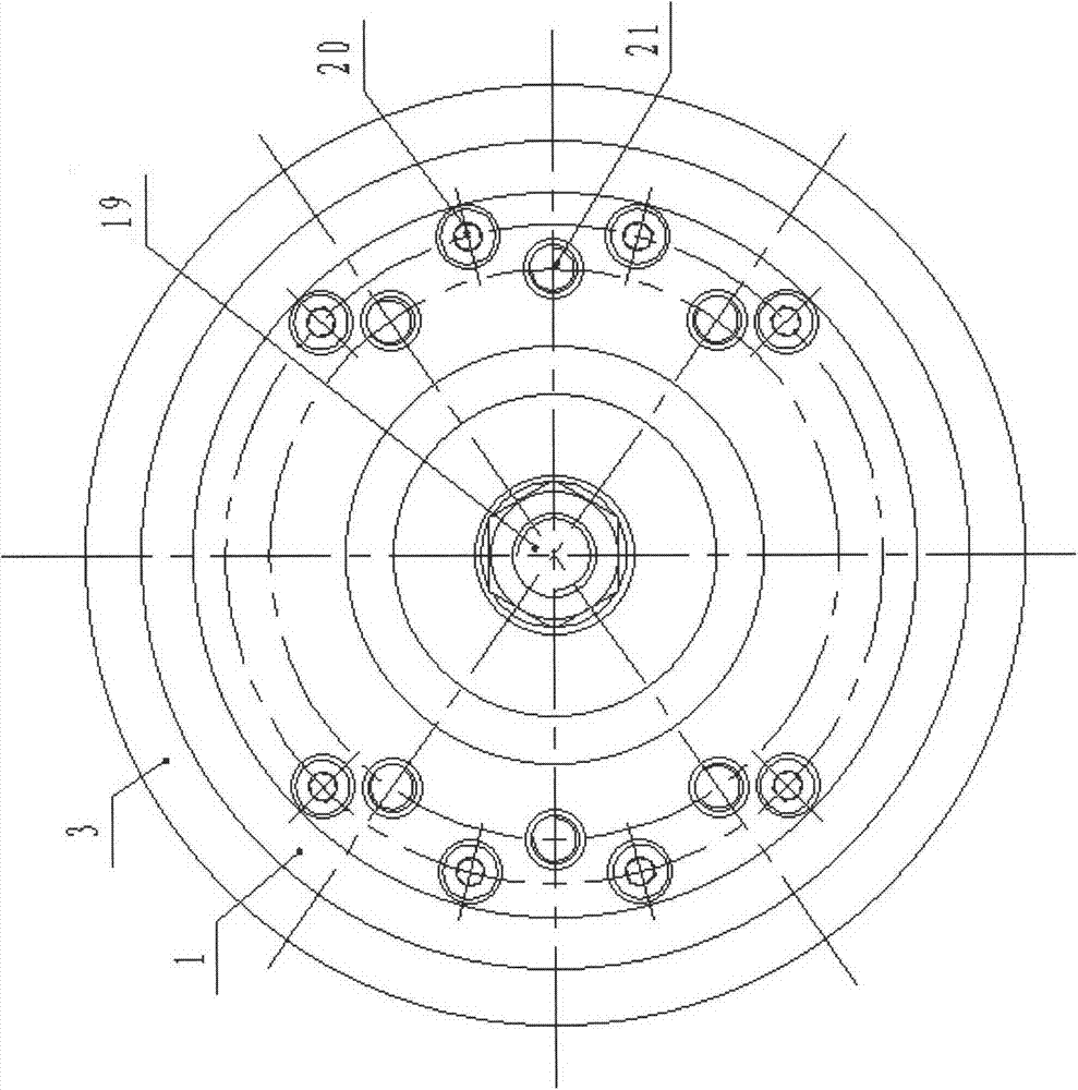
[0015] like figure 1 , figure 2 , image 3 , Figure 4 As shown, the telescopic chuck consists of a chuck seat (1), a center (10), a tie rod (19) and a chuck head. The chuck seat (1) is fixedly mounted on the machine tool spindle (22), and the center (10) Placed in the center of the front end of the chuck, the tail of the pull rod (19) protrudes from the center of the chuck seat (1) and is connected with the power of driving the chuck; A component on the sliding disc body (3) constitutes a chuck head, the chuck head is sleeved on the chuck seat (1) and the chuck core (8), and there are at least two or more clamping claws (6); (19) When pushed forward by external force, the chuck head extends forward, and after the chuck head reaches the limit position forward, the jaw (6) starts to clamp the workpiece; on the contrary, when the pull rod (19) ) is pulled backwards by external force, the jaws (6) release the workpiece, and the chuck head starts to retreat backwards only aft...


PUM


Abstract

A retractable chuck is composed of a chuck base, a centre, a pull rod and a chuck head. The chuck base is fixedly installed on a main shaft of a machine tool, the centre is placed in the center of the front end of the chuck, and the tail portion of the pull rod extends out of the center of the chuck base to be connected with the power of a drive chuck. The chuck head is formed by two or more clamping jaws, a sliding chuck body and an assembly arranged on the sliding chuck body, and the chuck head is arranged on the chuck base and a chuck chip in a sleeved mode. When the pull rod is pushed by external force to move forwards, the chuck head extends forwards, and only when the chuck head moves forwards and reaches the limiting position, the clamping jaws begin to clamp a workpiece. Or otherwise, when the pull rod is pulled by the external force to move backwards, the clamping jaws loose the workpiece, and only when the clamping jaws reach the limiting position, the chuck head begins to retreat backwards.

Description

technical field [0001] The invention relates to the field of machine tools, in particular to the chucks of common machine tools and numerically controlled machine tools. Background technique [0002] When processing shaft parts on ordinary machine tools and CNC machine tools, the chuck is the main tool for clamping the workpiece. With the rapid development of CNC machine tools, machining shaft parts on CNC machine tools, especially turning centers, can complete rough, fine, drilling, milling, tapping and other processes in one clamping. However, the current clamping of shaft parts The method still adopts the form of one end of the chuck and one end of the top. There are two processing techniques in this method: one is to leave the process chuck at one end of the workpiece at the chuck end, and one clamp and one top are processed, and the process clamp is cut off after completion. The second is to punch the center holes at both ends of the workpiece, one clamp and the other ...

Claims


Application Information

Patent Timeline
Patent Type & Authority Applications(China)
IPC IPC(8): B23B31/02
CPCB23B31/16
Inventor 党金行
Owner 山东济清科技服务有限公司
Why Eureka
Try Eureka