Circular electro-permanent magnetic chuck for vertical lathe

An electric permanent magnet chuck and circular technology, which is applied in the field of circular electric permanent magnet chuck for vertical lathes, can solve problems such as low processing efficiency, achieve the effects of good precision retention, stable state, and meet the needs of finishing

Inactive Publication Date: 2011-01-05
江苏无锡建华机床附件集团有限公司
View PDF8 Cites 2 Cited by
  • Summary
  • Abstract
  • Description
  • Claims
  • Application Information

AI Technical Summary

Problems solved by technology

One is to solve the problem of low processing efficiency. It is necessary to realize the goal of replacing the grinding process with the finishing process and effectively reduce the processing time; the other is to solve the unavoidable radial deformation caused by the chuck clamping thin-walled parts in the traditional turning process. The problem of deformation; the third is to solve the problem that one clamping can complete multi-faceted processing, so as to prevent processing errors caused by multiple clamping

Method used


Image

  • Circular electro-permanent magnetic chuck for vertical lathe
  • Circular electro-permanent magnetic chuck for vertical lathe
  • Circular electro-permanent magnetic chuck for vertical lathe

Examples


Embodiment Construction

[0010] Below the present invention will be further described in conjunction with the embodiment in the accompanying drawing:

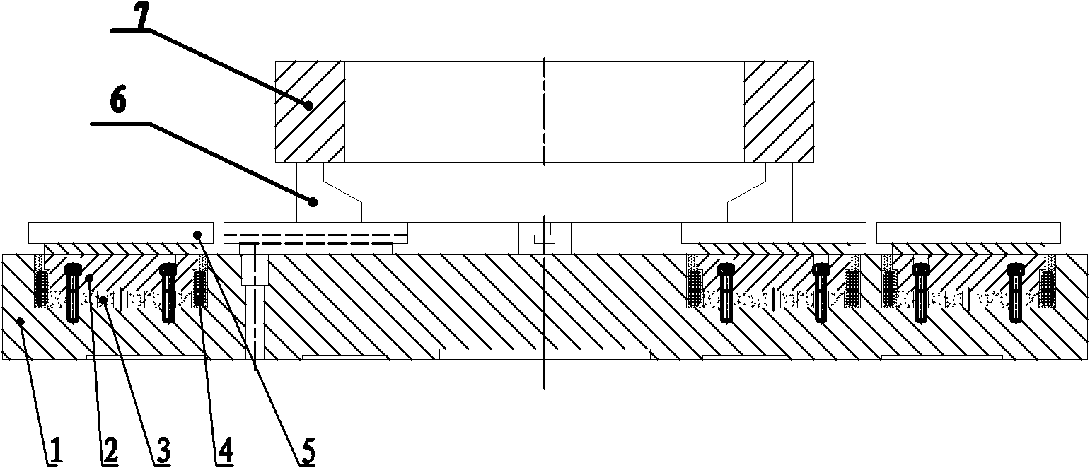
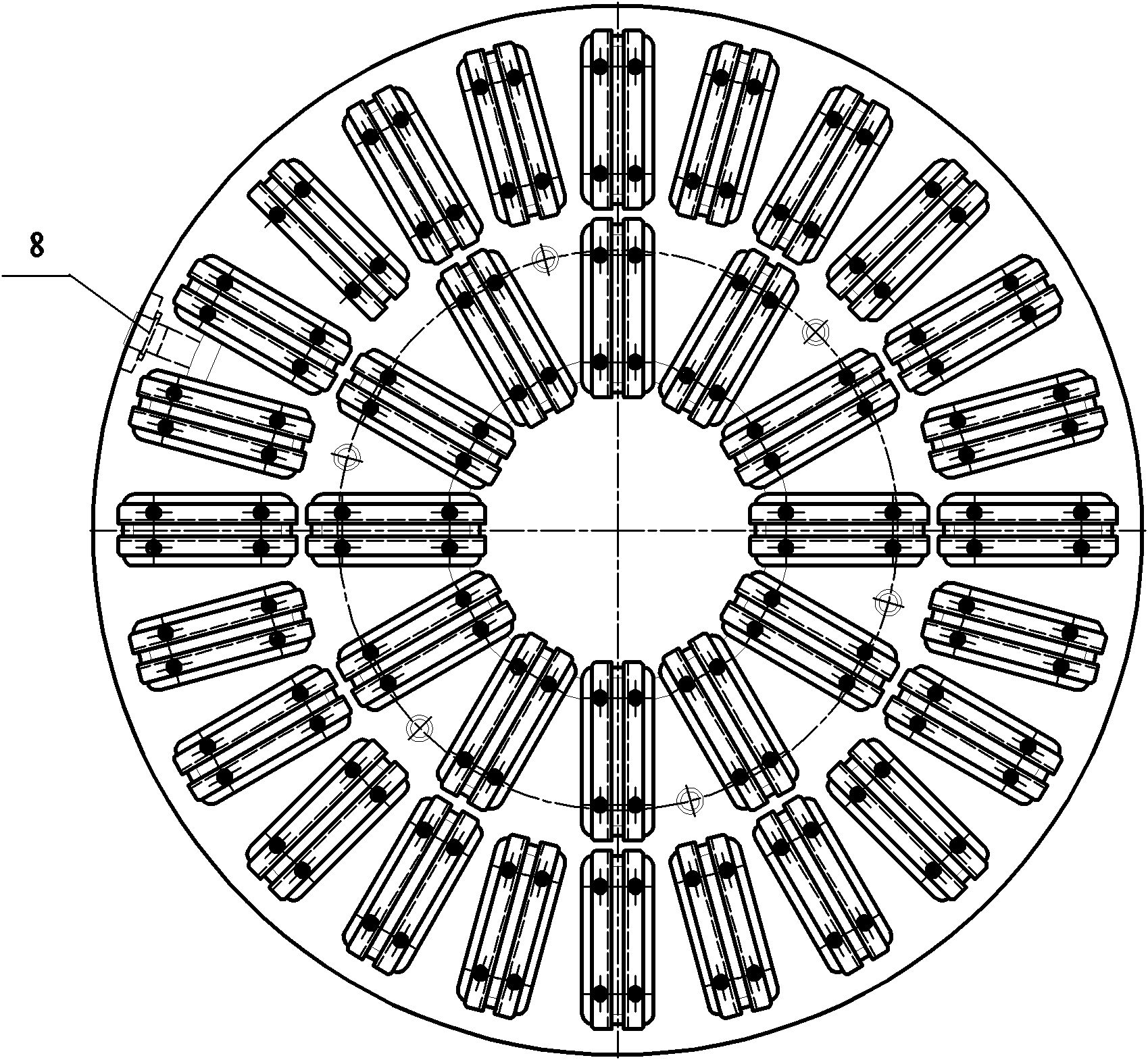
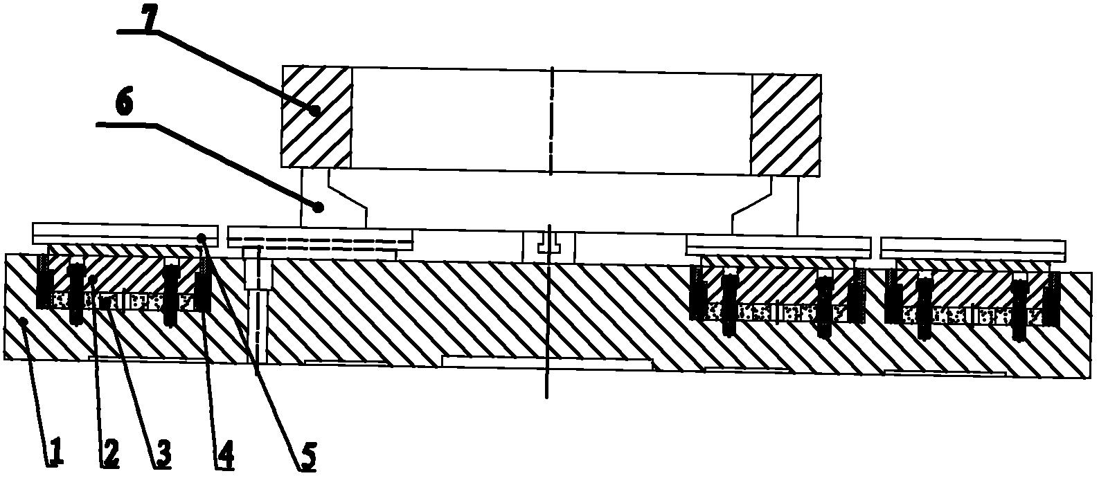
[0011] Such as Figure 1 ~ Figure 2 Shown: including disc body 1, magnetic pole 2, magnetic steel 3, excitation coil 4, magnetic pad 5, support block 6 and parts 7; a plurality of strip holes are arranged on the top of the disc body 1, and the magnetic pole 2 is pressed on the magnetic On the steel 3, the excitation coil 4 is installed on the outer ring of the magnetic steel 3, and the magnetic pad 5 is installed above the magnetic pole 2 to form a whole, and is installed in the strip hole above the disk body 1 with screws, and the wire of the magnetic pole 2 is led out of the disk body 1. The disc body 1 is equipped with a socket 8 .

[0012] Such as figure 2 As shown, it can be seen that the magnetic poles 2 on the disk body 1 are arranged in sections from the inside to the outside according to the size of the specification, the number of magnetic...


PUM


Abstract

The invention relates to a circular electro-permanent magnetic chuck for a vertical lathe, in particular to a magnetic fixture for a vertical lathe for realizing rapid machining by way of taking the place of grinding by turning. The circular electro-permanent magnetic chuck for a vertical lathe comprises a chuck body, magnetic poles, a magnetic steel, a magnet exciting coil and a magnetic cushion, wherein a plurality of strip-shaped holes are arranged above the chuck body, the magnetic poles are pressed on the magnetic steel, and the magnet exciting coil is arranged on an outer ring of the magnetic steel; the magnetic cushion is arranged above the magnetic poles, the magnetic cushion and the magnetic poles are integrated and arranged in the strip-shaped holes above the chuck body by bolts, and the wires of the magnetic poles are led out from the chuck body. The magnetic poles are straight-strip-shaped magnetic poles with same width. The two adjacent polarities of the straight-strip-shaped magnetic poles are opposite, and even magnetic poles are arranged on a same circumference in pairs. The invention has strong suction force, can satisfy the requirement for machining, has good retentivity of accuracy and stable state in the process of machining, can satisfy the requirement for finish machining, exempts the process of grinding, does not cause the phenomenon of divergent magnetic field, and can effectively avoid the influence of magnetic fields on cutting tools and iron filings in the process of machining.

Description

technical field [0001] The invention relates to a circular electro-permanent magnetic sucker for vertical lathes, in particular to vertical lathes using magnetic clamps for realizing rapid cutting with lathes instead of grinding. Background technique [0002] At present, with the development of the wind power industry, wind power companies have increased demand for wind power bearings, and the wind power bearing processing industry is in urgent need of a high-precision, high-efficiency turning fixture. One is to solve the problem of low processing efficiency. It is necessary to realize the goal of replacing the grinding process with the finishing process and effectively reduce the processing time; the other is to solve the unavoidable radial deformation caused by the chuck clamping thin-walled parts in the traditional turning process. The problem of deformation; the third is to solve the problem that one clamping can complete multi-faceted processing, so as to prevent proce...

Claims


Application Information

Patent Timeline
Patent Type & Authority Applications(China)
IPC IPC(8): B23Q3/154
Inventor 许峰唐彦华天虎韦鸣韩新强王猛张震宇宋昱
Owner 江苏无锡建华机床附件集团有限公司
Why Eureka
Try Eureka