Engine oil drainage valve

An engine and oil drainage technology, applied in the direction of engine components, machine/engine, engine lubrication, etc., can solve the problems of inconvenient installation and removal of plugs, limited oil collection space, and reduced engine maintenance.

Pending Publication Date: 2021-07-30
AECC HUNAN AVIATION POWERPLANT RES INST
View PDF6 Cites 1 Cited by
  • Summary
  • Abstract
  • Description
  • Claims
  • Application Information

AI Technical Summary

Problems solved by technology

[0005] 1) figure 1 The residual oil drainage structure shown is limited by the structure and the oil collection space is limited;
[0006] 2) figure 1 In the residual oil drainage structure shown, in order to avoid the leakage of high-pressure gas after the engine works normally, it needs to be blocked with a plug, and in order to drain the residual oil, it is necessary to remove the plug from time to time, which will reduce the maintainability of the engine;
However, there are generally many pipelines in the external space of the engine. Compared with small screws, the wrench for installing and removing the plug is relatively larger. In the case of limited operating space, it is inconvenient to install and remove the plug when the engine is being maintained in the field.

Method used


Image

  • Engine oil drainage valve
  • Engine oil drainage valve
  • Engine oil drainage valve

Examples


Embodiment Construction

[0041] The technical solutions of the present invention will be clearly and completely described below in conjunction with the embodiments. Apparently, the described embodiments are only some of the embodiments of the present invention, not all of them. Based on the embodiments of the present invention, all other embodiments obtained by persons of ordinary skill in the art without creative efforts fall within the protection scope of the present invention.

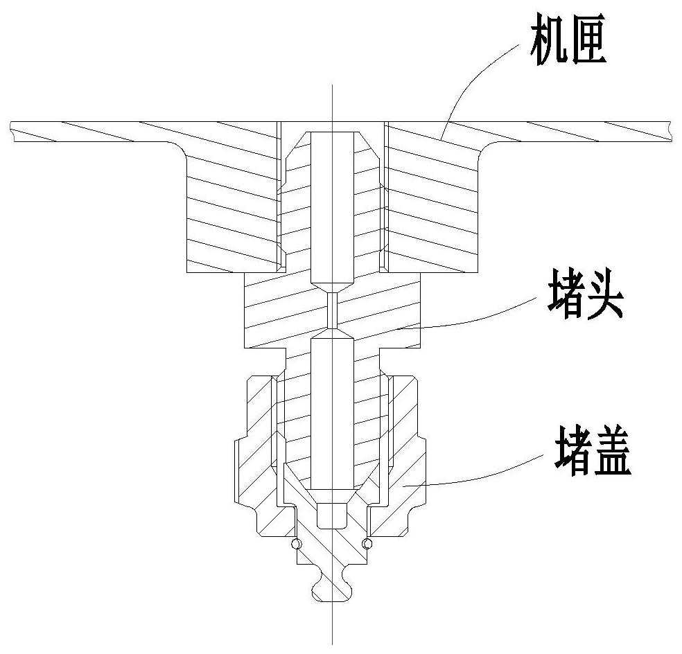
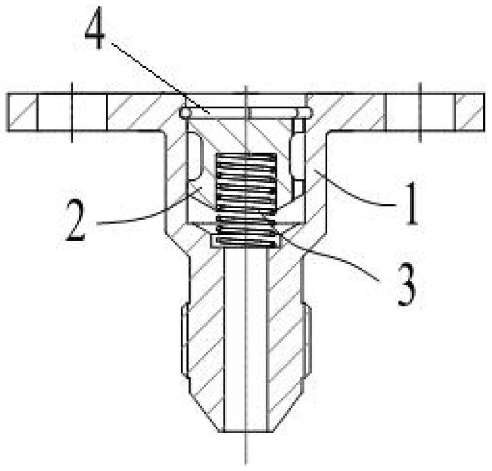
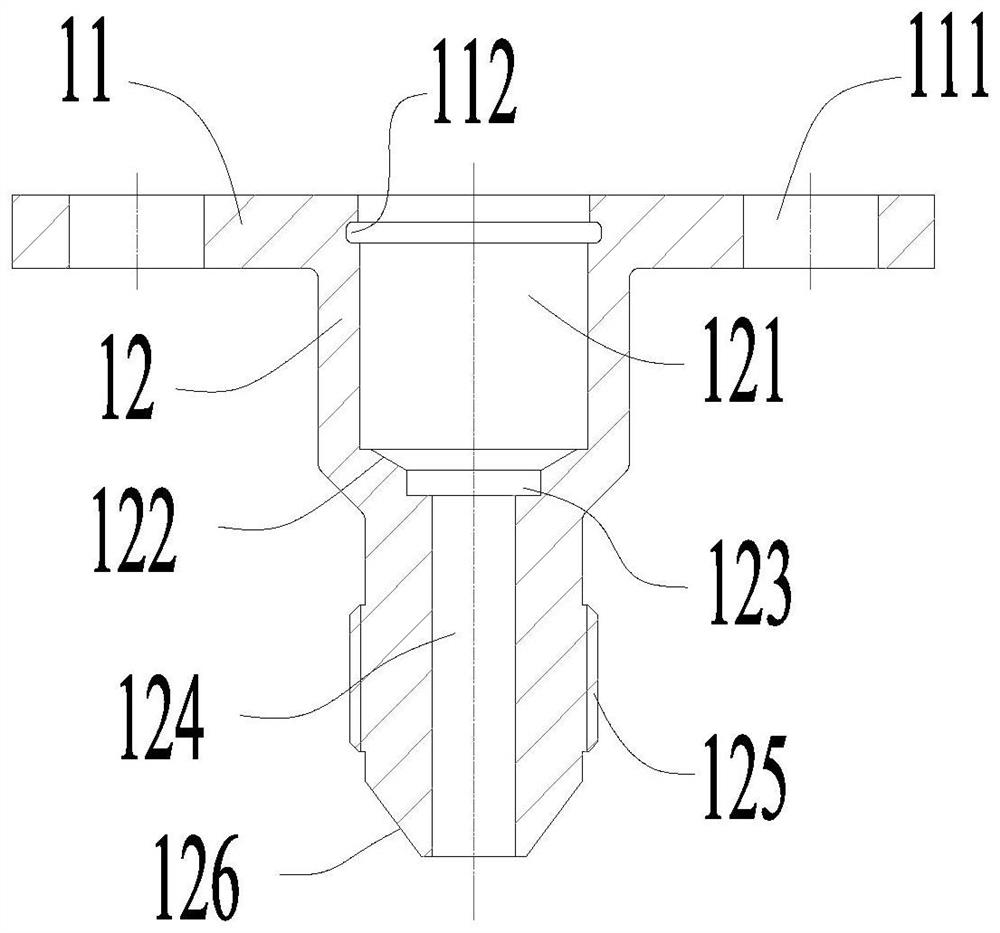
[0042] see Figure 2-6 As shown, an engine oil drain valve includes an oil drain seat 1, a valve 2, a spring 3 and a snap ring 4, the oil drain seat 1 is a hollow structure, and the oil drain seat 1 includes an inlet section 11 and a cylinder section 12, The inlet section 11 is provided with a mounting seat for the oil drain seat 1, which is waist-shaped or rectangular in structure, and two sets of screw mounting holes 111 are provided on the mounting seat, and a set of installation grooves are arranged in the inlet section...


PUM

PropertyMeasurementUnit
Diameteraaaaaaaaaa

Abstract

The invention discloses an engine oil drainage valve. The engine oil drainage valve comprises an oil drainage base, a valve body, a spring and a clamping ring, wherein the oil drainage base is of a hollow structure and comprises an inlet section and a cylinder section, a mounting base of the oil drainage base is arranged at the inlet section, two sets of screw mounting holes are formed in the mounting base, a set of mounting grooves are formed in the inlet section, the mounting groove is of an annular groove structure and is used for mounting a clamping ring, an inner cavity A, an inner cavity B and an inner cavity C are formed in the column body section, the inner cavity A is used for mounting a valve, the inner cavity B is used for mounting a spring, and the inner cavity C is used for providing a flow path for residual oil. By means of the design structure for sealing by the spring and a conical face, the instant, accurate and reliable switch-off of the oil drainage valve can be realized, and free switching of switch-on or switch-off of the oil drainage valve can be realized.

Description

technical field [0001] The invention belongs to the technical field of gas turbine engines, and in particular relates to an engine oil drain valve. Background technique [0002] During the use of the engine, if the engine fails to start once, a lot of fuel will be deposited in the combustion chamber. If the remaining oil is not discharged in time, when the engine is restarted, the remaining oil may cause deflagration, which may cause overheating of the engine ignition, and may be detrimental to the safety of the engine. And when the engine is working normally, it is necessary to avoid leakage of high-pressure gas, so as not to bring safety risks to the engine. Therefore, it is necessary to design an oil drain valve structure that is simple in structure, can quickly drain the residual oil in the combustion chamber and prevent air leakage after the engine works normally. [0003] At present, in order to drain the remaining oil, some engine combustion chambers use oil drain v...

Claims


Application Information

Patent Timeline
IPC IPC(8): F02M33/02F02B77/00
CPCF02M33/02F02M33/025F02B77/00F01M11/0408F01M2011/0416
Inventor 彭中九刘冉罗莲军陈丕敏陈盛蔡茂
Owner AECC HUNAN AVIATION POWERPLANT RES INST
Why Eureka
Try Eureka