Pneumatic load-removing plastic-sticking guiding rail

A guide rail and plastic sticking technology, applied in the direction of large fixed members, metal processing machinery parts, metal processing equipment, etc., can solve the problems of reducing the surface processing quality of the workpiece, high processing accuracy of the static pressure guide rail, and reducing the driving power of the worktable. Improve the quality of the machined surface, improve the machining accuracy, and avoid the effect of guide rail scratches

A guide rail and plastic sticking technology, applied in the direction of large fixed members, metal processing machinery parts, metal processing equipment, etc., can solve the problems of reducing the surface processing quality of the workpiece, high processing accuracy of the static pressure guide rail, and reducing the driving power of the worktable. Improve the quality of the machined surface, improve the machining accuracy, and avoid the effect of guide rail scratches

CN101125403BInactive Publication Date: 2010-05-19天津市第二机床有限公司

Image

  • Pneumatic load-removing plastic-sticking guiding rail
  • Pneumatic load-removing plastic-sticking guiding rail
  • Pneumatic load-removing plastic-sticking guiding rail

Examples


Embodiment Construction

[0017] Embodiments of the present invention will be further described below in conjunction with the accompanying drawings.

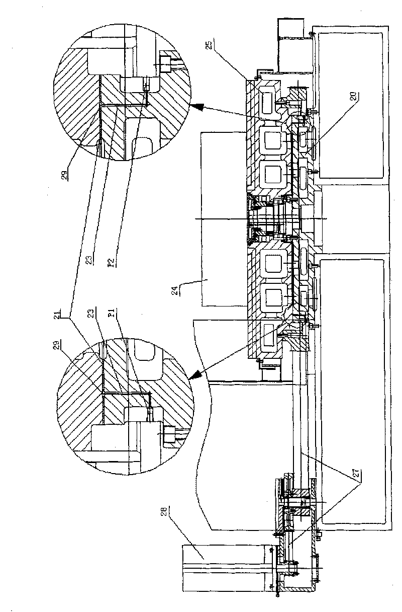
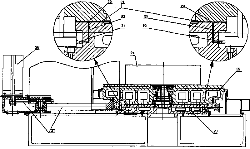
[0018] Such as figure 1 , figure 2 As shown, the present invention provides an air pressure unloading plastic-coated guide rail, which includes: a guide rail 20 ;

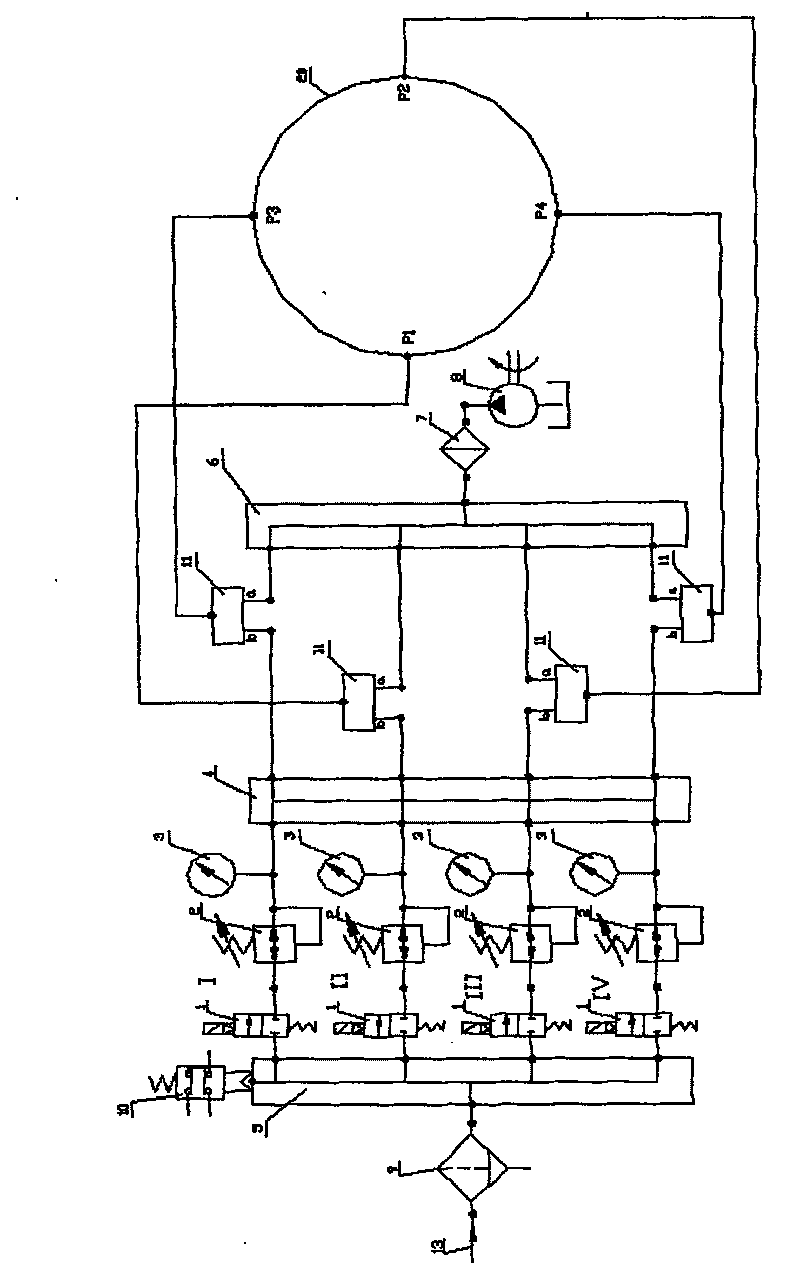
[0019] The surface of the guide rail 20 is bonded with a guide rail soft belt layer 21; oil and gas inlets P1, P2, P3, and P4 are arranged on the guide rail soft belt layer 21; 11, the gas regulating oil valve 11 has an oil circuit input terminal a and an air circuit input terminal b, the oil circuit input terminal a is connected in series with the oil filter 7 and the oil pump 8; the gas circuit input terminal b is connected in series The pressure gauge 3, pressure reducing valve 2, electromagnetic valve 1, and air filter 9 are connected to an air source 13, and the node between the air filter 9 and the electromagnetic valve 1 is connected to a pressure relay 10.

[0020] The guide rail ...


PUM


Abstract

The present invention discloses a pneumatic unloaded slideway coated with plastic, comprising a slideway and a worktable; the surface of the slideway is pasted with a flexible lacing layer which is provided with inlet ports of oil gas; every inlet port of oil gas is communicated with the output end of the control valve of the inlet port of oil gas, the control valve of oil gas has an oil pipelineinput end and a gas pipeline input end; the oil pipeline input end is connected with an oil filter and an oil pump in series and in sequence, and the gas pipeline input end is connected with a press gauge, a pressure relief valve, a magnetic valve, an air filter and the air source in series and in sequence; and a pressure relay is connected with the node of the air filter and magnetic valve. The present invention has the advantages that: the present invention is suitable for the variable machine tools, and the friction coefficient of the flexible lacing layer of slideway is low. The present has good self-lubricating performance, thereby avoiding the scratching of the slideway; the precision of the slideway is increased, the noise and the vibration are reduced and the surfaced process quality of element is improved. The present invention applies compression air to mix with the lubricant which is pumped out by the control valve of oil gas and the oil pump, and then the oil gas is supplied to the flexible lacing layer of the slideway; thus, the burden of the slideway is unloaded at 70-80 percent, thereby reducing the rotary friction of the worktable.

Description

technical field [0001] The invention relates to a guide rail for sliding fit of a workbench, in particular to an air pressure unloading and plastic-coated guide rail. Background technique [0002] In the prior art, guide rails with sliding fit of worktables are often used in the design of machine tools. There are several typical structures for circular worktable guide rails that rotate around the vertical axis: The first structure: metal-to-metal sliding circular guide rails, due to the large friction , low life, now no longer used in CNC machine tools. The second structure: metal-to-metal sliding circular guide rail, but in order to improve the service life and reduce the friction coefficient, Babbitt alloy with low friction coefficient and low hardness is cast on one side of the guide rail pair. The precision and service life of this guide rail structure are both It is better than the first one, but because the friction force is still large, the accuracy cannot be maintai...

Claims


Application Information

Patent Timeline
19 May 2010
Publication
CN101125403B
IPC
B23Q1/38
Inventors
赵仲淦; 潘高星