Method for active explosion proofing and explosion suppression through high-pressure inert gas

A high-pressure inert gas, explosion-proof and explosion-suppressing technology is applied in earth drilling, safety devices, mining equipment, etc. It can solve the problems of long disaster avoidance routes, complex network systems, and difficulty in accurately judging the source of explosions, and achieve the goal of isolating external Explosion propagation, preventing gas explosion accidents, and reducing the effect of shock wave intensity

Inactive Publication Date: 2014-05-14
CHINA UNIV OF MINING & TECH
View PDF6 Cites 18 Cited by
  • Summary
  • Abstract
  • Description
  • Claims
  • Application Information

AI Technical Summary

Problems solved by technology

[0004] First, it is difficult to accurately determine the source of explosion
Since the gas will diffuse and move into the ventilation network with the wind flow in the restricted roadway, once it diffuses and touches a suitable ignition source, it will explode, and it is actually difficult to judge when and where it will encounter the accident fire source ( The occurrence of the accident fire source is

Method used


Image

  • Method for active explosion proofing and explosion suppression through high-pressure inert gas
  • Method for active explosion proofing and explosion suppression through high-pressure inert gas
  • Method for active explosion proofing and explosion suppression through high-pressure inert gas

Examples


Embodiment Construction

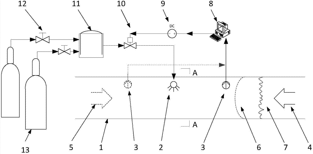
[0020] An embodiment of the present invention will be further described below in conjunction with the accompanying drawings: the role of the pressure reducing valve 12?

[0021] The active explosion-proof and explosion-suppression method of high-pressure inert gas of the present invention, concrete steps are as follows:

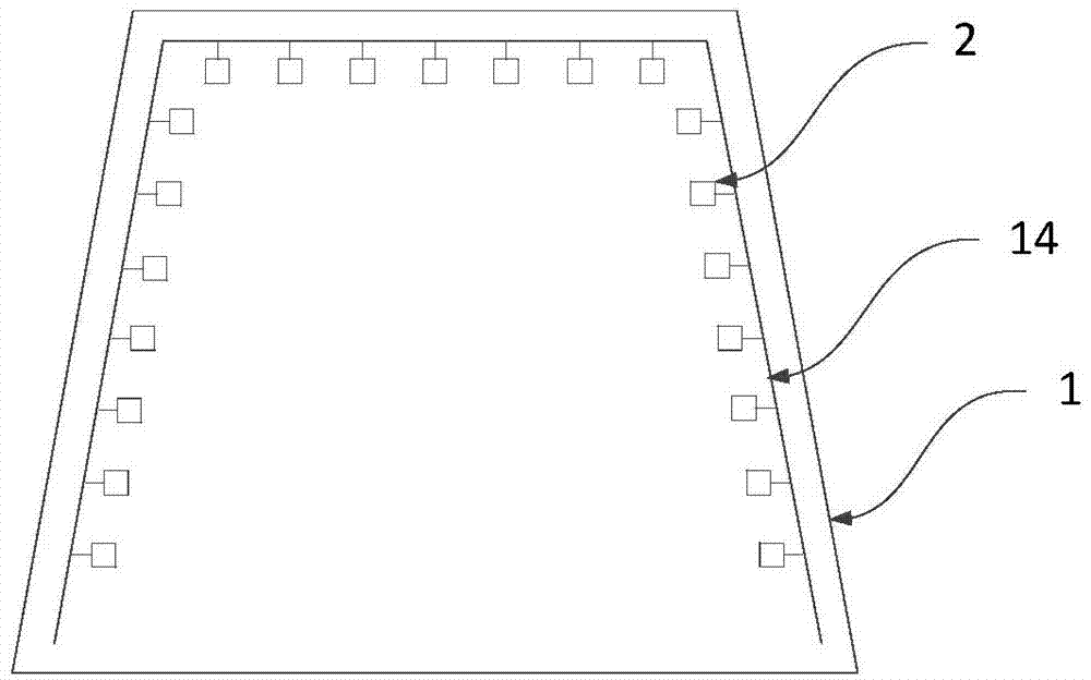
[0022] a. A plurality of injectors 2 are arranged at intervals in an array on the side of the roadway 1 and the roof. The plurality of injectors 2 are connected through the high-pressure rubber hose 14, and the signal processing system 8 is connected to the roadway on both sides of the injector 2. Pressure sensor 3; the distance between multiple injectors 2 arranged in an array on the side of the roadway 1 and the roof is <20cm; the linear distance between the injector 2 and the pressure sensor 3 is 18-22m;

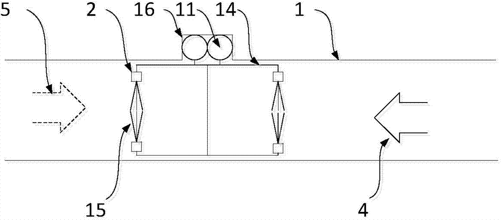
[0023] b. Construct a wall groove 16 in the side lane where the injector 2 is arranged, and set a high-pressure inert gas source 13 and a gas storage ta...


PUM


Abstract

Provided is a method for active explosion proofing and explosion suppression through high-pressure inert gas. The method for active explosion proofing and explosion suppression through the high-pressure inert gas is applicable to prevention and suppression of gas explosions in a closed pipeline without external decompression space, and is particularly applicable to prevention and suppression of gas explosions in a coal mine. The method for active explosion proofing and explosion suppression through the high-pressure inert gas comprises the steps that wall grooves are constructed in a mine laneway, and a high-pressure gas source and a signal receiving and processing system are installed; a plurality of ejectors are distributed on the laneway side and a roof in an array mode at intervals, the ejectors are communicated through high-pressure rubber hoses, and pressure sensors which are connected with the signal receiving and processing system are arranged in the portions, on the two sides of each ejector, of the laneway respectively, wherein the laneway side and the roof are arranged on the same section of the mine laneway; the sensors are installed in the laneway, and receive shock wave signals, and the high-pressure inert gas source ejectors and connecting pipelines of the high-pressure inert gas source ejectors are installed; when the gas explosions happen, the sensors detect the forwards-moving shock wave signals, a solenoid valve is started, gas of the high-pressure inert gas source is ejected through the ejectors, a high-pressure inert gas curtain is formed in the laneway, and spread of explosion shock waves is obstructed.

Description

technical field [0001] The invention relates to an active explosion isolation and suppression method for high-pressure inert gas, which is especially suitable for tunnels where gas explosions occur in coal mines, and is also suitable for explosion isolation and suppression of other industrial pipelines that transport combustible gases with explosion hazards. Background technique [0002] The major threat to the safe production of gas explosion coal mines is still the main accident form that causes casualties and property losses in mines. For this reason, major coal-producing countries such as the United States, Russia, Poland, and Germany have established large-scale underground explosion test tunnels of different sizes. , developed various automatic explosion-proof devices and passive explosion-proof sheds with sensitive actions and good spray effects. In order to solve the practical problems of coal mine safety production, our country attaches great importance to organizin...

Claims


Application Information

Patent Timeline
IPC IPC(8): E21F5/08
Inventor 朱传杰林柏泉刘谦江丙友洪溢都孙豫敏
Owner CHINA UNIV OF MINING & TECH
Why Eureka
Try Eureka