Stabilizing foot piece

A technology for stabilizing feet and supporting parts, applied to the frame of the engine, supporting machines, mechanical equipment, etc., can solve troubles and other problems, and achieve the effect of falling smoothly

Inactive Publication Date: 2014-05-14
QINGDAO TECHCAL UNIV QINDAO COLLEGE
View PDF8 Cites 4 Cited by
  • Summary
  • Abstract
  • Description
  • Claims
  • Application Information

AI Technical Summary

Problems solved by technology

The falling object is likely to need to be adjusted horizontally, so the master worker needs

Method used


Image

  • Stabilizing foot piece
  • Stabilizing foot piece
  • Stabilizing foot piece

Examples


Embodiment Construction

[0015] The structural composition and working principle of the present invention will be further described in detail below in conjunction with the accompanying drawings and specific embodiments.

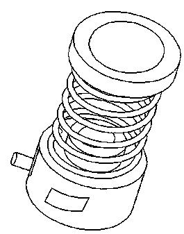
[0016] A stable foot, which is composed of a supporting part and a lifting part, is characterized in that the supporting part is connected with the lifting part.

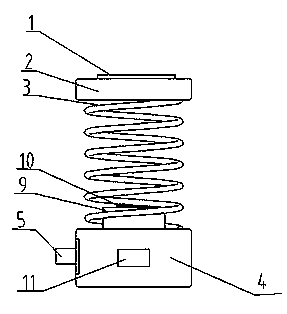
[0017] The supporting part is composed of a magnetic body 1, a supporting body 2, a spring 3 and a base 4, wherein the magnetic body 1 is connected to the supporting body 2, one end of the spring 3 is connected to the supporting body 2, and the other end of the spring 3 is connected to the base 4.

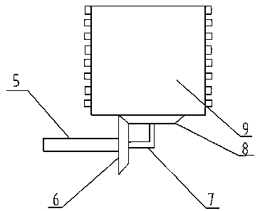
[0018] The lifting part is composed of a rotating shaft 5, a vertical bevel gear 6, a connecting bent shaft 7, a horizontal bevel gear 8, a rotating top body 9, a pressure sensor 10, and a display screen 11, wherein the rotating shaft 5 is connected to the vertical bevel gear 6 , the vertical bevel gear 6 is connected with ...


PUM


Abstract

The invention relates to a stabilizing foot piece. By the aid of the stabilizing foot piece, the problem of consumption of large quantities of human and material resources and energy for safely and stably dropping mechanical devices under normal circumstances due to deficiency of special devices for safely dropping objects in the prior art can be solved. The stabilizing foot piece comprises a supporting portion and a lifting portion. An elastic support can be sucked on the surface of an object. The stabilizing foot piece has the advantages that heavy objects can be effectively prevented from being violently collided with the ground to be damaged in dropping procedures, large mechanical devices can be stably dropped by the stabilizing foot piece, and the height of a certain position of the object further can be adjusted by the aid of the stabilizing foot piece.

Description

technical field [0001] The invention relates to a support device, in particular to a stable foot. Background technique [0002] The so-called support refers to withstand the pressure so that things do not collapse, but it is far from enough to support the object, and the object needs to be stabilized. But in order to make the object stable, it is necessary to adjust the height of each point of the object, and finally make the object stable. One way that people often choose is to adjust the height of each point of the object through the cushion body, and finally make the object stable, but this adjustment method is time-consuming and laborious. In the mechanical assembly workshop, the take-off and landing of mechanical devices is a relatively frequent link. When the heavy object is lowered to the point of contact with the ground, the falling speed needs to be reduced rapidly. Once the speed control is wrong, the mechanical device will collide violently with the ground, and ...

Claims


Application Information

Patent Timeline
IPC IPC(8): F16M7/00
Inventor 韩振五张霞
Owner QINGDAO TECHCAL UNIV QINDAO COLLEGE
Why Eureka
Try Eureka