In-place auxiliary device for switch cabinet

A technology for auxiliary devices and switch cabinets, applied in switchgear, substation/switch layout details, electrical components, etc., can solve problems such as endangering personal and equipment safety, irregular operation behavior, and low work efficiency, so as to reduce the number of people and process Easy to make, simple structure effect

Inactive Publication Date: 2014-05-14
STATE GRID CORP OF CHINA +3
View PDF7 Cites 4 Cited by
  • Summary
  • Abstract
  • Description
  • Claims
  • Application Information

AI Technical Summary

Problems solved by technology

The whole process of putting in place is carried out by everyone shouldering their hands, and at the same time, 7 to 8 people are required to work at the same time. The switchgear needs a lot of labor and the work efficiency is low.
At the same time, during the process of installing the switchgear on the foundation of the cabinet body, the construction personnel's work behavior is not standardized, and sometimes under the condition of uneven force, the cabinet body will fall sideways, endangering the safety of people and equipment

Method used


Image

  • In-place auxiliary device for switch cabinet

Examples


Embodiment Construction

[0012] Below the present invention will be further described in conjunction with the embodiment in the accompanying drawing:

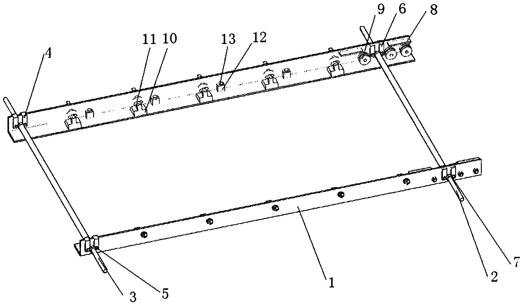
[0013] Such as figure 1 As shown, the present invention mainly includes two symmetrically arranged rails 1. The front ends of the two rails 1 are connected by a front disengagement rod 2, and a front nut bayonet 6 is provided at the connection between the two rails 1 and the front disengagement rod 2. , The front nut bayonet 6 is clamped with the front disengagement nut 7, and the front disengagement nut 7 is threadedly connected with the front disengagement rod 2. When the front disengagement lever 2 is turned, the front disengagement nut 7 can drive the two rails 1 to shrink inwardly, so as to narrow the distance between the two rails 1; when the front disengagement lever 2 is turned in the other direction, the front disengagement nut 7 7 can drive the two tracks 1 to expand outward, so as to increase the distance between the two tracks 1 .

[0014...


PUM


Abstract

The invention relates to an auxiliary device, in particular to an in-place auxiliary device for a switch cabinet, and belongs to the technical field of electric power construction. The in-place auxiliary device comprises two rails arranged in bilateral symmetry, the front ends of the two rails are connected through a front separating rod, front nut clamping openings are formed in the positions, connected with the front separating rod, of the two rails, front separating nuts are clamped in the front nut clamping openings, and the front separating nuts are connected with the front separating rod through threads. The rear ends of the two rails are connected through a rear separating rod, rear nut clamping openings are formed in the positions, connected with the rear separating rod, of the two rails, rear separating nuts are clamped in the rear nut clamping openings, and the rear separating nuts are connected with the rear separating rod through threads. According to the in-place auxiliary device, work staff can save more labor in the switch cabinet in-place process, a cabinet body moves stably and cannot topple over, the number of persons in the switch cabinet in-place matching process is greatly reduced, the in-place efficiency of the switch cabinet can be improved in multiples, and the cabinet body in-place time is shortened.

Description

technical field [0001] The invention relates to an auxiliary device, in particular to an auxiliary device for positioning a switch cabinet, and belongs to the technical field of electric power construction. Background technique [0002] During the construction process of the power construction team, the switchgear installation is the main work content of the substation and distribution substation infrastructure, accounting for more than 30% of the entire project time. It is a process that requires the most manpower and takes the longest time. It takes 7- It takes 8 people and takes 15 minutes to complete the placement of a single cabinet. With the rapid development of the local economy, the demand for electricity is increasing rapidly. In recent years, the number of infrastructure projects of power construction teams has increased day by day, and the amount of infrastructure projects of power construction teams has increased year by year at a rate of 20%, but the number of ...

Claims


Application Information

Patent Timeline
Patent Type & Authority Applications(China)
IPC IPC(8): H02B3/00H02B1/50
Inventor 潘金祥任赟俞新旭周德伟高浩
Owner STATE GRID CORP OF CHINA
Why Eureka
Try Eureka