
Punctuality compensating circuit and method for pulse per second

A compensation circuit and second pulse technology, which is applied in electrical components, digital transmission systems, transmission systems, etc., can solve problems that affect the accuracy of second pulse, the accuracy cannot be guaranteed, and the time synchronization device loses its punctuality, so as to achieve the effect of correcting errors

Active Publication Date: 2014-05-14
SICHUAN JIUZHOU ELECTRIC GROUP
View PDF2 Cites 10 Cited by
  • Summary
  • Abstract
  • Description
  • Claims
  • Application Information

AI Technical Summary

Problems solved by technology

[0003] At present, the commonly used timekeeping method is realized by aligning with the second signal of the receiver every second. The accuracy of this timekeeping method mainly depends on the accuracy of the second signal received by the timing receiver. cannot be guaranteed, causing the time synchronization device to lose its punctuality
In the time synchronization device, the crystal oscillator frequency division counting can also be used to keep time, but as we all know, the crystal oscillator itself has problems such as temperature drift or aging rate that will inevitably affect the accuracy of the crystal oscillator, which will directly affect the accuracy of the second pulse. Causes the time synchronization device to lose its punctuality

Method used

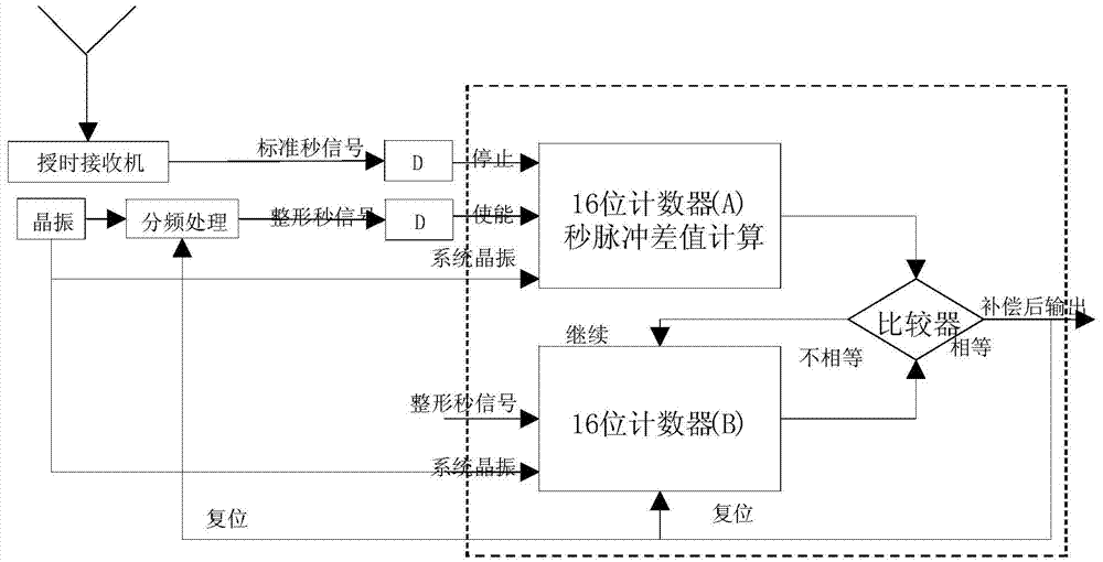
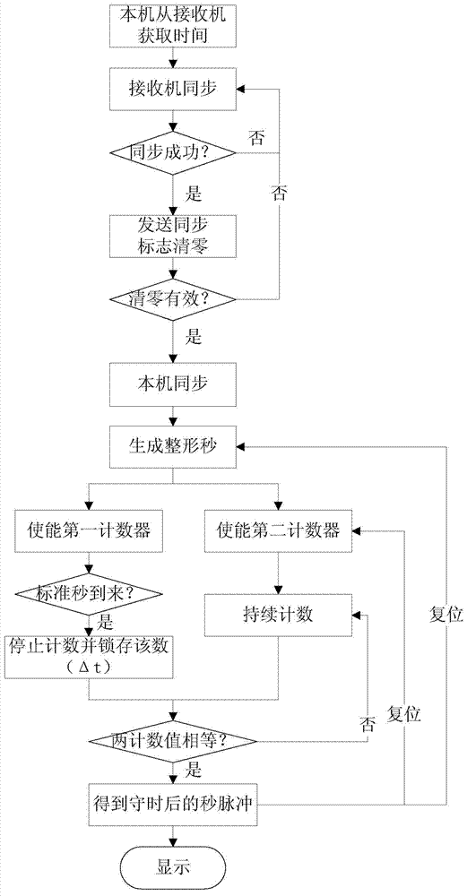
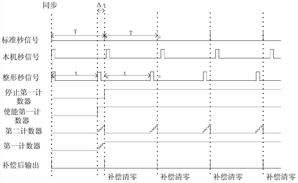

Image

  • Punctuality compensating circuit and method for pulse per second
  • Punctuality compensating circuit and method for pulse per second
  • Punctuality compensating circuit and method for pulse per second

Examples


Embodiment Construction

[0031] The following will clearly and completely describe the technical solutions in the embodiments of the present invention with reference to the drawings in the embodiments of the present invention. Apparently, the described embodiments are preferred implementation modes for implementing the present invention, and the description is for the purpose of illustrating the general principle of the present invention, and is not intended to limit the scope of the present invention. The scope of protection of the present invention should be defined by the claims. Based on the embodiments of the present invention, all other embodiments obtained by those of ordinary skill in the art without creative efforts belong to the protection of the present invention. range.

[0032] Commonly used time keeping methods are basically realized by aligning the second signal of the receiver every second. Specifically, the receiver (such as GPS receiver, etc.) obtains the standard second pulse (PPS, ...


PUM


Abstract

The invention relates to the technical field of time synchronization and discloses a punctuality compensating circuit and method for a pulse per second. The punctuality compensating circuit comprises a time service receiver, a crystal oscillator, a frequency division processing unit, a first counter, a second counter and a comparator, wherein the time service receiver provides standard second signals; the crystal oscillator provides system crystal oscillator signals; the frequency division processing unit processes the system crystal oscillator signals to provide shaped second signals; the shaped second signals enable the first counter to count the system crystal oscillator signals, and then the first counter is controlled by the standard second signals to stop and latch counting; the shaped second signals enable the second counter to count the system crystal oscillator signals; the comparator outputs pulse per second signals generated after punctuality compensation when the count values of the two counters are equal, and the frequency division processing unit and the second counter are reset through the pulse per second signals respectively. According to the punctuality compensating circuit and method for the pulse per second, a deviation compensation mode for punctuality signals is provided, crystal oscillator errors are effectively corrected, and high-precision punctuality is guaranteed.

Description

technical field [0001] The invention relates to the technical field of time synchronization, in particular to a second pulse punctuality compensation circuit and method. Background technique [0002] The time synchronization device realizes time synchronization through time service. The time service methods mainly include satellite time service, short wave time service, long wave time service, Internet and telephone time service, etc. Time synchronization devices are used in a wide range of fields. For example, in the field of financial securities, slight errors will lead to huge economic losses; in the power industry, personal safety and public property will also be threatened due to the poor accuracy of time synchronization devices; , The high-precision time synchronization device can improve the characteristics of weapons and improve the national defense strength of our country; these fields have strict requirements on the accuracy of time, so a high-precision time synchr...

Claims


Application Information

Patent Timeline
IPC IPC(8): H04L7/033
Inventor 曾勤波李军
Owner SICHUAN JIUZHOU ELECTRIC GROUP
Learn More