Combined structure of cooling fins and shell body

A heat dissipation fin and combined structure technology, which is applied in the direction of cooling/ventilation/heating transformation, electrical equipment shell/cabinet/drawer, electrical components, etc., can solve the problem of easy falling off of heat dissipation fins, high work intensity of workers, and unfavorable heat conduction and other problems to achieve the effect of preventing falling off, ensuring heat dissipation capacity, and preventing waste

Inactive Publication Date: 2014-05-14
MARCHESI METAL TECH SUZHOU
View PDF3 Cites 2 Cited by
  • Summary
  • Abstract
  • Description
  • Claims
  • Application Information

AI Technical Summary

Problems solved by technology

This structure has the following disadvantages: 1. The heat dissipation fins are bonded to the heat dissipation shell with glue. Glue is a material with poor thermal conductivity. The glue between the shell and the fins is not conducive to heat conduction and reduces heat dissipation efficiency.
2. The heat dissipation fins need to wait for the heat dissipation shell of the casting to be bonded by manual operation. The production efficiency is low and the work intensity of the workers is high.
3. The heat dissipation fins are bonded to the aluminum shell, and the heat dissipation fins are easy to fall off, thereby reducing the heat dissipation capacity

Method used


Image

  • Combined structure of cooling fins and shell body
  • Combined structure of cooling fins and shell body
  • Combined structure of cooling fins and shell body

Examples


Embodiment Construction

[0026] The present invention will be described in detail below with reference to the accompanying drawings and in combination with embodiments.

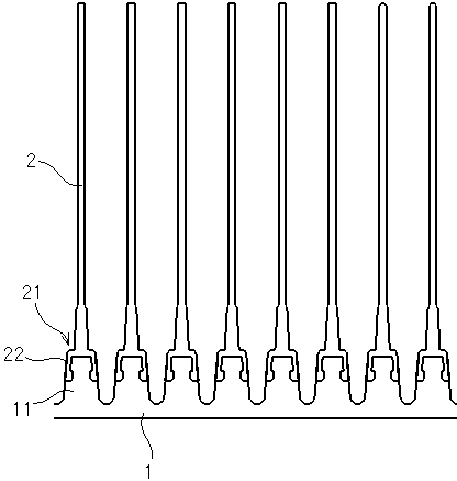
[0027] refer to figure 1 As shown, a combined structure of a heat dissipation fin and a housing includes a heat dissipation housing 1 and a heat dissipation fin 2. A plurality of elongated bosses 11 are uniformly arranged on the heat dissipation housing 1. The heat dissipation fins 2 The bottom 21 of the bottom 21 is insert-cast on the boss 11 of the heat dissipation housing 1 . The bottom 21 of the heat dissipation fin 2 is hollow and open, with skirts 22 on both sides. The bottom of the skirt 22 is folded inward, and the boss 11 is inlaid and cast in the skirt 22 .

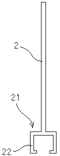
[0028] refer to figure 2 As shown, in Embodiment 1, the hollow structure inside the skirt 22 is rectangular.

[0029] refer to image 3 As shown, in Embodiment 2, the hollow structure inside the skirt 22 is circular.

[0030] refer to Figure 4 As shown, in Embo...


PUM


Abstract

The invention discloses a combined structure of cooling fins and a shell body. The combined structure of the cooling fins and the shell body comprises the cooling shell body and the cooling fins, wherein a plurality of long strip-shaped bosses are evenly arranged on the cooling shell body, the bottom of each cooling fin is embedded and cast on the corresponding boss of the cooling shell body, the bottom of each cooling fin is of a hollow bottom surface open structure, the two sides of the bottom of each cooling fin are skirts, the bottom of each skirt is folded inwards, and each boss is embedded and cast inside the corresponding skirts. The skirts of the bottom of each cooling fin wrap the corresponding boss, casting internal stress is effectively reduced, and deformation is prevented. The bottom of each cooling fin is of the hollow bottom surface open structure, and waste of materials caused by flowing out of molten metal in the casting process is prevented.

Description

technical field [0001] The invention relates to the field of heat dissipation equipment, in particular to a combined structure of heat dissipation fins and a housing. Background technique [0002] With the continuous development of electronic technology, the power of equipment is getting higher and higher, and the requirements for heat dissipation are getting higher and higher. In addition, outdoor electronic equipment needs waterproof, windproof and other protection. Outdoor electronic equipment often uses non-ferrous alloy casting shells as shells. The general design is die-casting shells. The inner space formed by the box cover is used to place printed circuit boards (PCB) or other equipment. , to play a protective role, and design cooling fins on the outside of the shell to help the equipment dissipate heat naturally. [0003] In the existing heat dissipation fins of electronic equipment, the aluminum casing is first cast, and then the heat dissipation fins are bonded t...

Claims


Application Information

Patent Timeline
Patent Type & Authority Applications(China)
IPC IPC(8): H05K5/00H05K7/20
Inventor 陈卫国康薇茹
Owner MARCHESI METAL TECH SUZHOU
Why Eureka
Try Eureka