
Heat sink

A heat dissipation shell and heat dissipation fin technology, which is applied in the direction of cooling/ventilation/heating transformation, casing/cabinet/drawer components, etc., can solve the problems of high labor intensity, low production efficiency, poor thermal conductivity, etc. , to achieve the effect of high labor intensity, low production efficiency and improved heat dissipation efficiency

Active Publication Date: 2016-05-25
MARCHESI METAL TECH SUZHOU
View PDF10 Cites 0 Cited by
  • Summary
  • Abstract
  • Description
  • Claims
  • Application Information

AI Technical Summary

Problems solved by technology

This structure has the following disadvantages: 1. The copper tube is bonded to the shell, resulting in uneven inner surface of the shell, which is not conducive to full contact with the heating device and reduces heat dissipation efficiency
2. The copper tube is bonded to the shell with glue. Glue is a material with poor thermal conductivity. The glue between the shell and the copper tube is not conducive to heat conduction and reduces heat dissipation efficiency.
3. Copper pipe bonding needs to wait for the heat dissipation shell of the casting to be made and bonded manually. The production efficiency is low and the work intensity of the workers is high.

Method used


Image

  • Heat sink
  • Heat sink
  • Heat sink

Examples


Embodiment Construction

[0021] The present invention will be described in detail below with reference to the accompanying drawings and in combination with embodiments.

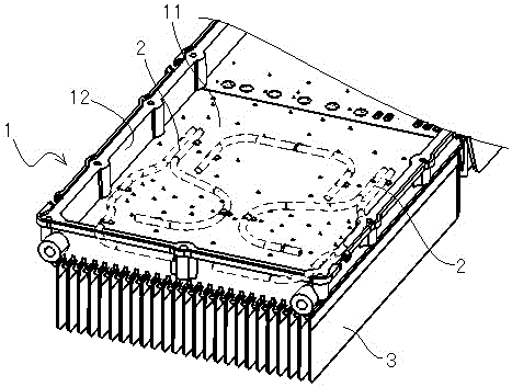
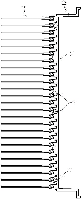
[0022] refer to figure 1 , figure 2 As shown, a heat dissipation housing includes a heat dissipation housing 1 composed of a top wall 11 and a side wall 12 and a copper pipe 2 , and the copper pipe 2 is arranged inside the top wall 11 .

[0023] According to a preferred embodiment of the present invention, the copper pipe 2 is embedded and cast in the top wall 11 of the heat dissipation housing 1 .

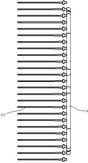
[0024] refer to figure 2 , image 3 , Figure 4 As shown, looking further, there are multiple cooling fins 3 connected to the top wall 11 . The copper pipe 2 is in direct contact with the heat dissipation fins 3 .

[0025] It can be seen from the above text description and in conjunction with the accompanying drawings that after adopting the present invention, the copper tube 2 is arranged inside the heat dissipation shell 1, whi...


PUM


Abstract

The invention discloses a radiation shell which comprises a radiation shell consisting of a top wall and a side wall, and copper tubes, wherein the copper tubes are arranged in the top wall in an embedding and casting way. According to the radiation shell, the copper tubes are arranged in the radiation shell, so that the problem that the copper tubes are adhered to cause the unevenness of the inner surface of the radiation shell is solved, and a heating device is fully contacted with the inner wall of the radiation shell to facilitate the conduction of heat and improve the radiation efficiency; the copper tubes are arranged in the radiation shell, so that the problem that glue for adhering the copper tubes is unfavorable for the heat conduction is solved, and the contact area of the glue and the copper tubes is enlarged so that the radiation efficiency is further improved.

Description

technical field [0001] The invention relates to a heat dissipation shell, in particular to a heat dissipation shell with high heat dissipation efficiency. Background technique [0002] With the continuous development of electronic technology, the power of equipment is getting higher and higher, and the requirements for heat dissipation are getting higher and higher. In addition, outdoor electronic equipment needs waterproof, windproof and other protection. Outdoor electronic equipment often uses non-ferrous alloy casting shells as shells. The general design is die-casting shells. The inner space formed by the box cover is used to place printed circuit boards (PCB) or other equipment. , to play a protective role, and design cooling fins on the outside of the shell to help the equipment dissipate heat naturally. [0003] In the existing heat dissipation shell, the shell is first cast, and then the copper pipe is bonded to the shell. This structure has the following disadvant...

Claims


Application Information

Patent Timeline
Patent Type & Authority Patents(China)
IPC IPC(8): H05K7/20H05K5/02
Inventor 陈卫国康薇茹
Owner MARCHESI METAL TECH SUZHOU
Learn More