Mechanism and chair for powered combined and independent seat back and leg rest motion

A power-driven, independent motion technology, used in chairs, reclining chairs, other seating furniture, etc., to solve the problem of inability to operate footrests and backrests independently

Active Publication Date: 2014-05-14
LA-Z-BOY
View PDF6 Cites 11 Cited by
  • Summary
  • Abstract
  • Description
  • Claims
  • Application Information

AI Technical Summary

Problems solved by technology

Such a design generally cannot independently operate the foot rest and the backrest

Method used


Image

  • Mechanism and chair for powered combined and independent seat back and leg rest motion
  • Mechanism and chair for powered combined and independent seat back and leg rest motion
  • Mechanism and chair for powered combined and independent seat back and leg rest motion

Examples


Embodiment Construction

[0031] Embodiments of the present invention will now be described in more detail with reference to the accompanying drawings.

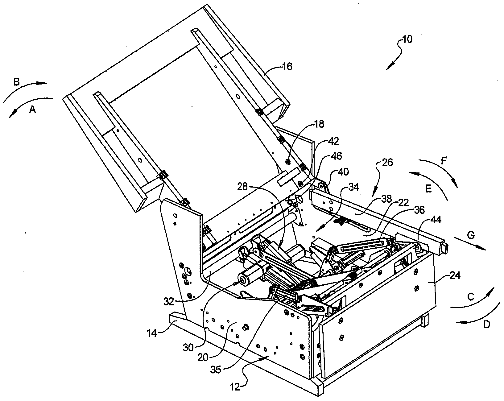
[0032] Such as figure 1 As shown, the furniture 10 includes a furniture support assembly 12 rotatably supported on a base 14 . The backrest 16 is rotatably connected to the furniture support assembly 12, and can rotate from the fully upright position toward the direction A of lying on the back, or return to the fully upright position from the fully lying position toward the returning direction B of the backrest, or Any position between a fully upright position and a fully reclined position. The back rest 16 is passed through the swivel connectors 18 opposite to each other (only one of which can be clearly seen in figure 1 ) is rotatably connected to the furniture support assembly 12. The furniture stand assembly 12 includes a first side member 20 and a second side member 22 for a user seated on the furniture 10 . The first side member 20 is on the...


PUM


Abstract

A furniture member mechanism includes a first actuator device electrically operated to displace first and second seat back actuation links connected to and operating to rotate a seat back member between upright and fully reclined positions. A pantograph linkage set connected to a leg rest member is at least partially supported in an extended position by rotational contact with a support rod. A second actuator device identical to the first actuator device is electrically operated to axially rotate a drive rod connected to a drive link. The drive link is connected to and displaces the pantograph linkage set between the stowed and extended positions. A swing lever rotatably connected to the support rod is rotated during operation of the second actuator device to extend the pantograph linkage set. The swing lever in a fully rotated position displaces the support rod creating a furniture member tilt position.

Description

technical field [0001] The present invention relates to a furniture mechanism with powered joint and independent movement of the backrest and footrest. Background technique [0002] This section provides background information about the invention which is not necessarily prior disclosed art. [0003] Furniture such as chairs, sofas, loveseats, and ottomans generally include a mechanism that allows the user to manually move the footrest from the stowed position to the open position to support the foot, and, independently of moving the footrest In order to make the backrest rotate from a straight state to a fully lying state, it generally requires the user to apply weight / power. There are also some actuators on the market now, which can provide power to drive or automatically move the footrest, and then provide power to drive the backrest. Such designs generally need to open the footrest first, and then rotate the backrest. To reset the position, The actuator first rotates t...

Claims


Application Information

Patent Timeline
IPC IPC(8): A47C17/04A47C1/032A47C1/034
CPCA47C1/0242A47C7/5068A47C1/03211A47C1/0342A47C7/462A47C7/506A47C17/04A47C31/126
Inventor 理查德·E.·马歇尔尤金·II·科尔拉里·P.·拉普安特查德·E.·亚当斯
Owner LA-Z-BOY
Why Eureka
Try Eureka