Trolley wire wear measuring device

a technology of wear measurement and trolley wire, which is applied in the direction of structural/machine measurement, instruments, and using mechanical means, can solve the problems of difficult to measure the thickness of the long distance section in a short time, and achieve the effect of convenient wear measuremen

Active Publication Date: 2009-12-31
MEIDENSHA ELECTRIC MFG CO LTD
View PDF3 Cites 31 Cited by
  • Summary
  • Abstract
  • Description
  • Claims
  • Application Information

AI Technical Summary

Benefits of technology

[0016]It is therefore an object of the present invention to provide a wear measuring device of the trolley wire, which ensures the wear measurement over the entire section of the trolley

Problems solved by technology

(1) In the case of the method that directly measures the thickness of the trolley wire using the ruler such as the vernier caliper, since the operator performs the measurement by hand and also the measurement requires manpower and cannot be automated, it is difficult to measure the thickness of the long distance section in a short time.
(2) In the case of the method that directly measures the thickness of the trolley wire using the optical sensor, because the measurement involves the contact between the rotation roller and the trolley wire, the low speed operation is required. In addition, since the measurement structure in which the trolley wire is sandwiched between the sensors is employed, the usage in the place where the structure that is apt

Method used


Image

  • Trolley wire wear measuring device
  • Trolley wire wear measuring device
  • Trolley wire wear measuring device

Examples


embodiment 1

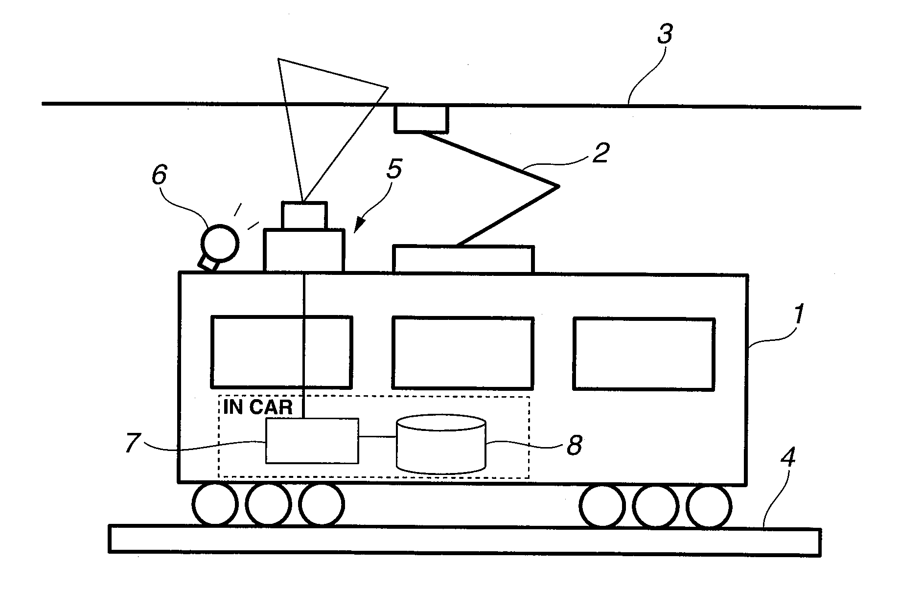
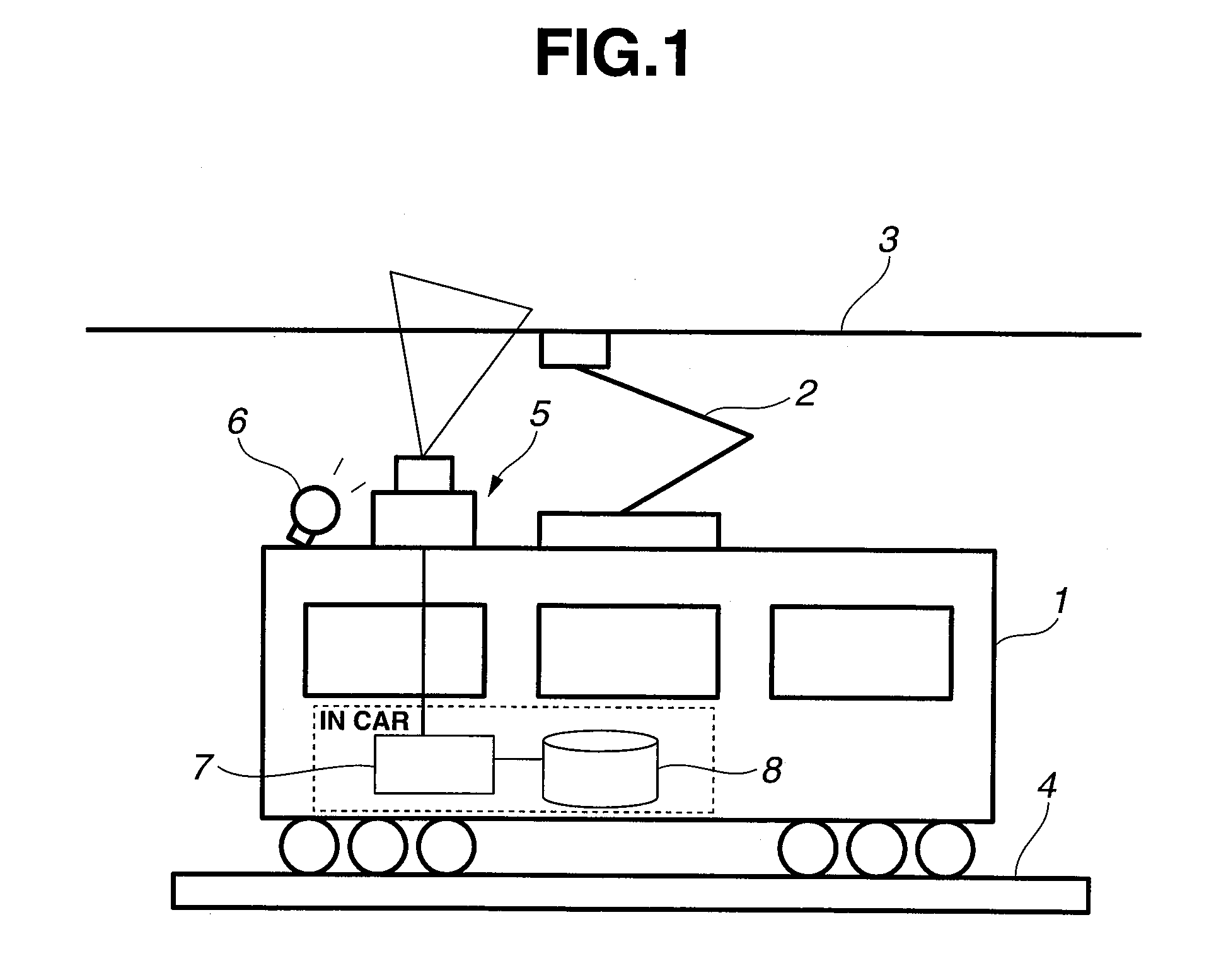
[0044]FIG. 1 is a system diagram of a wear measuring device of a trolley wire, of an embodiment of the present invention, which performs the wear measurement of the trolley wire during daytime.

[0045]A test car 1 collects current from a trolley wire 3 through a pantograph 2 that is mounted on a roof of the car, and is capable of running on a rail along the trolley wire 3 by a motor drive of wheels, same as a passenger car. This test car 1 is provided with a line sensor 5 and an illumination lamp 6, as a photography image input means of the trolley wire 3, on the roof. And a measurement computer 7 and a recording device 8 are installed in the car.

[0046]The line sensor 5 is placed in a direction of a scanning line perpendicular to a laying direction of the trolley wire of a wear measurement target, and shoots a pantograph contact surface of the trolley wire while moving along the trolley wire. For this reason, the line sensor 5 is installed vertically so that the line sensor 5 faces in...

embodiment 2

[0069]Usually, the trolley wire side surface is shot as the black portion due to rust or soot. The trolley wire worn portion is shot as the white, as compared with the side surface, by applying strong illumination (FIG. 5A).

[0070]Through the use of this, in the present embodiment, since the trolley wire worn portion exists in a sandwiched state between the black lines of the trolley wire side surfaces in the removal of the sky parts from “the binary operated line sensor image” in the embodiment 1, the trolley wire side surface is extracted first, then only the white portion existing inside the side surface is extracted (FIG. 5B).

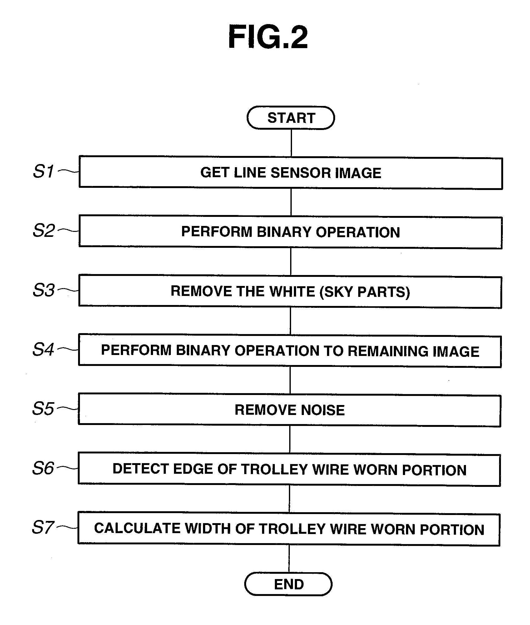
[0071]A flow chart of this process is shown in FIG. 6. The trolley wire side surface is extracted from the line sensor image obtained (S8), and a binary operation process is executed to an area inside this side surface (S9), which are different from FIG. 2. Further, a system of this device is shown in FIG. 7. A trolley wire side surface extraction process se...

embodiment 3

[0073]In the present embodiment, with respect to the removal of the sky parts from “the binary operated line sensor image” in the embodiment 1, as a different manner of the removal of the sky parts, as shown in a system diagram in FIG. 8, two line sensors are provided, and one line sensor 5A shoots a portion of the trolley wire 3 illuminated by the illumination lamp 6 (FIG. 9B), and the other line sensor 5B shoots non-light-applied trolley wire 3 (FIG. 9A). And by getting a difference obtained from them, only a worn area that is illuminated is emphatically extracted (FIG. 9C).

[0074]A flow chart of this process is shown in FIG. 10. An image shot by the line sensor 5A is obtained (S10), and an image shot by the line sensor 5B is obtained (S11), then by performing a differential operation of the both images, the line sensor image in which the illuminated worn area is emphasized, is obtained (S12), which are different from FIG. 2. Further, a system of this device is shown in FIG. 11. Th...


PUM


Abstract

[Object] To ensure a wear measurement over an entire section of a trolley wire and to facilitate the wear measurement, and also to perform the measurement during daytime, without being affected by structures existing around the trolley wire.
[Means to solve] A line sensor 5 and an illumination lamp 6, which are placed in a direction of a scanning line perpendicular to a laying direction of a trolley wire, are mounted on a test car 1. The line sensor 5 shoots a pantograph contact surface of the trolley wire by the running of the test car, and this image signal is saved in a recording device 8 through a measurement computer 7. The measurement computer 7 arranges luminance signals of scanning lines, obtained by the line sensor 5, in time series, and creates a line sensor image. The measurement computer 7 gets a binary operated line sensor image from this line sensor image. The measurement computer 7 further removes sky parts from this binary operated line sensor image and detects edges of a trolley wire worn portion, then determines a width of the trolley wire worn portion through an overall width of the trolley wire and a height, viewed from the line sensor, of the trolley wire.

Description

TECHNICAL FIELD[0001]The present invention relates to a device for measuring wear of a pantograph contact surface of a trolley wire, and more particularly to a wear measuring device that determines a width of the pantograph contact surface through a photography image of the trolley wire then measures a thickness of the trolley wire from this width.BACKGROUND ART[0002]On the trolley wire that supplies a power to a car of an electric railroad or railway, contact with a pantograph current collector (a pantograph) occurs each time the car passes. Because of this, the trolley wire is gradually worn out during an operation of the electric railway car, and if a replacement is not made, a rupture or breaking finally occurs and causes an accident. A wear limit is then set for the trolley wire. By using the wear limit as an index of a change of the trolley wire, the trolley wire is changed and safety of the electric railway car is secured.[0003]As a method of measuring the wear of the trolley...

Claims


Application Information

Patent Timeline
IPC IPC(8): G01N3/56
CPCG01B11/24B60M1/28G01B11/16G01M5/0033
Inventor WATABE, YUSUKENIWAKAWA, MAKOTO
Owner MEIDENSHA ELECTRIC MFG CO LTD
Why Eureka
Try Eureka