Device for measuring electromagnetic field intensity

a technology of electromagnetic field intensity and electrical instrumentation, which is applied in the direction of electric digital data processing, electric dynamic magnetometers, instruments, etc., can solve the problems of low sensitivity to electromagnetic field (emf) amplitude, device has low sensitivity to electromagnetic wave incidence angle, damage to objects

Inactive Publication Date: 2015-07-07
KOROTKOV KONSTANTIN G
View PDF14 Cites 0 Cited by
  • Summary
  • Abstract
  • Description
  • Claims
  • Application Information

AI Technical Summary

Benefits of technology

[0012]It is an object of the present invention to provide a possibility for detecting a useful signal in a wide range of frequencies, as well as for performing remote measurement of electromagnetic field intensity in automatic mode.

Problems solved by technology

A known device for detecting high-power microwave pulsed radiation can be used for establishing the fact of irradiation of an object with the specified radiation, which can result in damage to the object.
The disadvantage of this technical solution consists in low sensitivity towards electromagnetic field (EMF) amplitude, because the EFM intensity must be quite high for the discharge to occur, since both sides of the gap have an identical original potential.
In addition, the device has low sensitivity towards the incidence angle of the electromagnetic wave.
It should also be mentioned that said device only records the fact of presence or absence of the EMF and does not allow determining quantitative characteristics of the field.
Thus in order to increase field sensitivity it is necessary to reduce the gap width, however significant reduction of the gap leads to a real possibility of short circuit.
Sensitivity of the known device is insufficient, because it is limited by the geometric shape of the electrodes and the minimal allowed width of the gap therebetween.
The disadvantage of the prototype device consists in that the abovementioned circuit has a fixed resonance frequency, which does not allow detecting a useful signal in a wide range of frequencies.
Besides, another disadvantage of the prototype consists in the absence of a possibility to remotely measure the electromagnetic field intensity, including its measurement in automatic mode.

Method used


Image

  • Device for measuring electromagnetic field intensity
  • Device for measuring electromagnetic field intensity
  • Device for measuring electromagnetic field intensity

Examples


Embodiment Construction

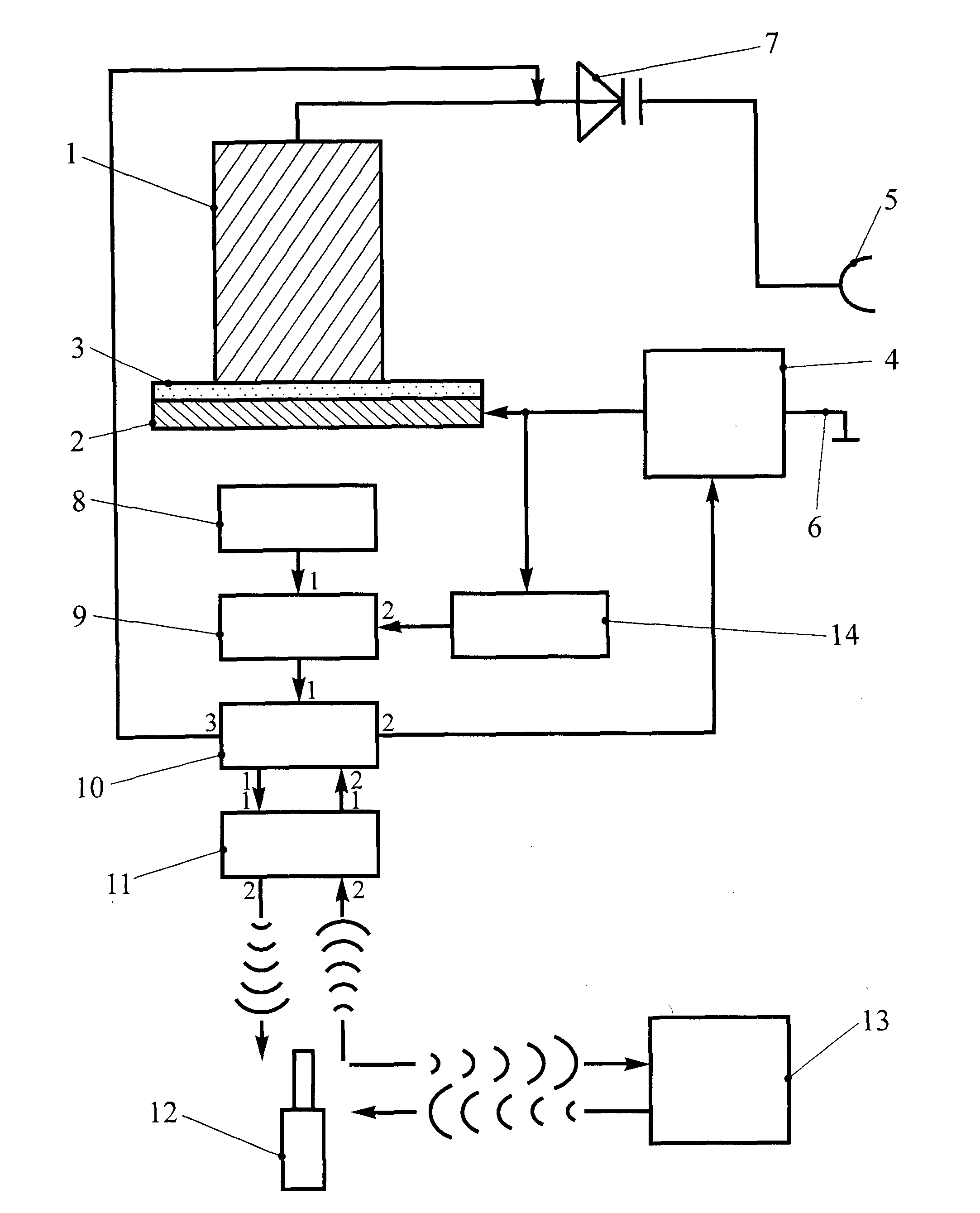
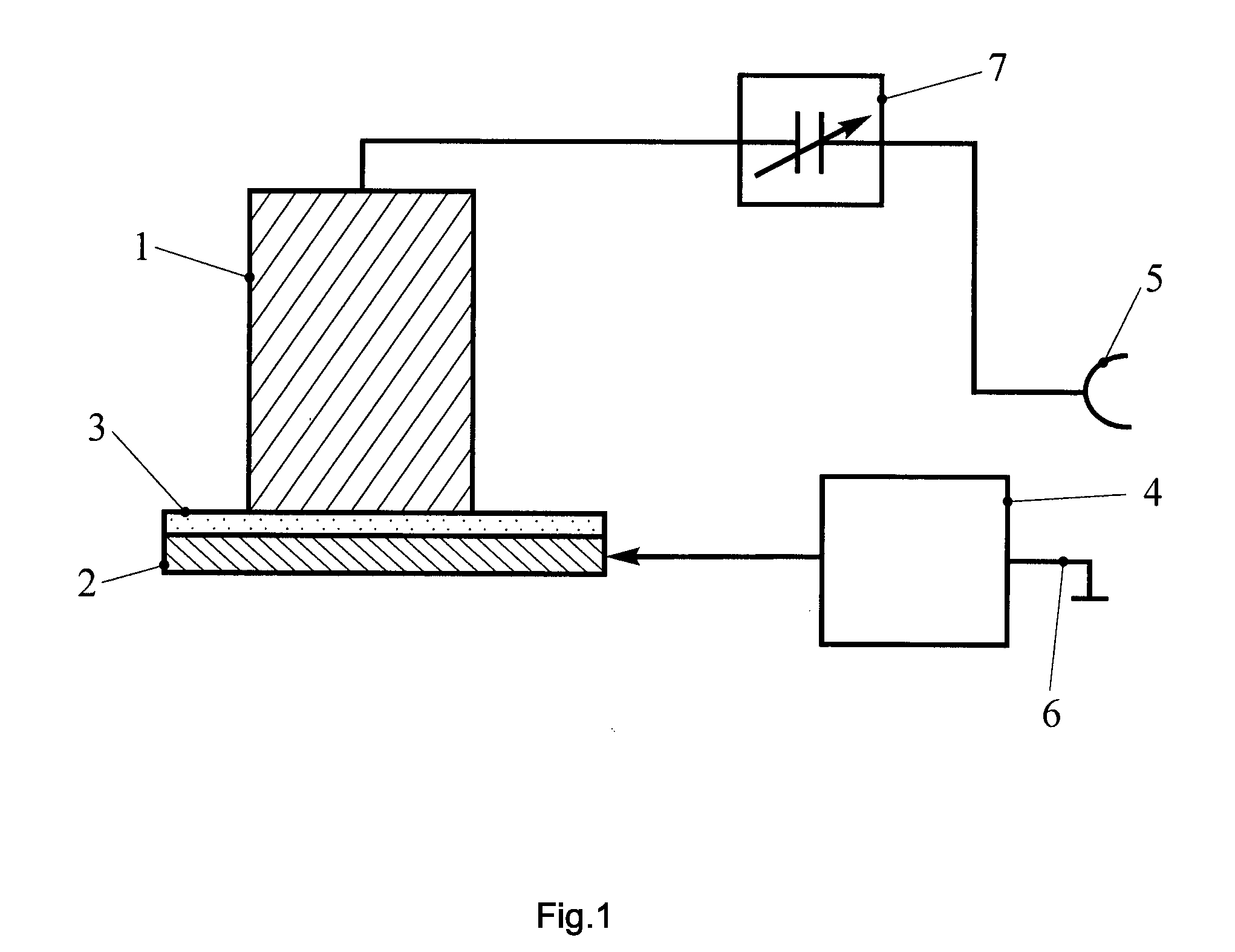
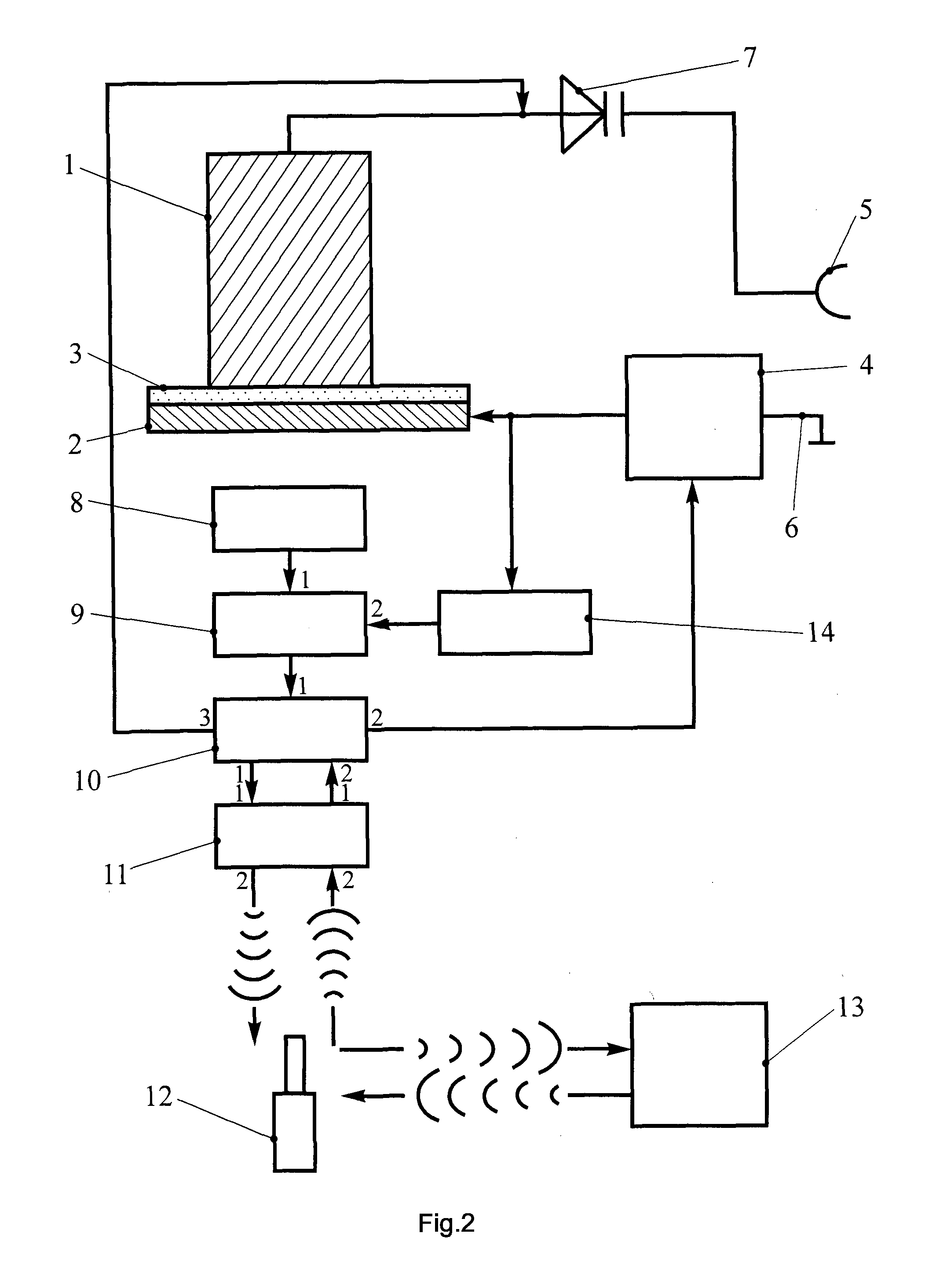
[0018]The device comprises a measuring instrument for recording the glow of a gas discharge and a gas-discharge chamber that is formed between electrodes 1 and 2; electrode 1 is cylindrical, in this particular example it is made of titanium, which ensures its durability under conditions of a gas discharge. Electrode 1 can also be made of tungsten, niobium etc. Diameter of electrode 1 in this particular example is 10 mm. Electrode 2 is in the shape of a disk with diameter of 80 mm, which in an embodiment of the invention according to claim 1 is a metal plate. In an embodiment of the invention according to claim 3 the electrode 2 is made of a transparent current-conducting material, in particular a polymer material or a ultra-thin transparent metallic film, which is applied using spatter or deposition to the dielectric plate 3 that separates electrodes 1 and 2. Plate 3 is 3 mm wide and is made of quartz. Other dielectrics can be used, including glass. Vertical symmetry axis of the cyl...


PUM


Abstract

The invention relates to gas-discharge electrical instrumentation technology. The device for measuring electromagnetic field intensity comprises a measuring instrument for recording the glow of a gas discharge and a gas-discharge chamber that is formed between electrodes 1 and 2 separated by a dielectric 3. The electrode 1 is cylindrical, while the electrode 2 is in the form of a disk. The electrodes 1 and 2 are coupled to an electrical voltage source, wherein a capacitive element in the form of a pair comprising an antenna 5 and a connection to ground 6 is incorporated into the line coupling the cylindrical electrode 1 to the electrical voltage source. A capacitor 7 with variable capacitance is incorporated into the line coupling the cylindrical electrode 1 to the antenna 5. The technical result consists in providing the possibility of detecting a useful signal in a wide frequency range.

Description

TECHNICAL FIELD[0001]The invention relates to gas-discharge electrical instrumentation technology and can be used, in particular, for obtaining objective data during biolocation.BACKGROUND ART[0002]A known device for detecting high-power microwave pulsed radiation can be used for establishing the fact of irradiation of an object with the specified radiation, which can result in damage to the object. Said device comprises a plate made of a conductive material and provided with one or more gaps therein. The gaps are filled with air or another dielectric. If the plate is subjected to pulsed radiation, the electromagnetic field intensity in the gaps is increased. If the field intensity exceeds the electrical strength of the dielectric in the gap, a gas-discharge breakdown occurs through the gap. The light flash that corresponds to the discharge is recorded on tape, see WO 9836286 A1.[0003]The disadvantage of this technical solution consists in low sensitivity towards electromagnetic fie...

Claims


Application Information

Patent Timeline
Patent Type & Authority Patents(United States)
IPC IPC(8): G01R13/04G01R29/08G01R33/028G02B1/00
CPCG01R29/0878G02B1/00G01R33/028G06Q2230/00G06F2101/00G02B2207/00G01R29/0871
Inventor KOROTKOV, KONSTANTIN G.
Owner KOROTKOV KONSTANTIN G
Why Eureka
Try Eureka