Turbine housing and exhaust gas turbine supercharger

A technology of turbine casing and turbine impeller, which is applied in the direction of machines/engines, gas turbine devices, mechanical equipment, etc.

Inactive Publication Date: 2014-05-14
TOYOTA JIDOSHA KK
View PDF5 Cites 5 Cited by
  • Summary
  • Abstract
  • Description
  • Claims
  • Application Information

AI Technical Summary

Problems solved by technology

[0005] According to this configuration, since the distal portion of the impeller housing member (5) can slide in the axial direction of the turbine impeller (9), it is possible to limit the temperature due to the outer housing member (2) and the discharge pipe (10). Reduced external forces acting on the impeller housing member (5) in the direction towards the blades of the turbine impeller (9)

Method used


Image

  • Turbine housing and exhaust gas turbine supercharger
  • Turbine housing and exhaust gas turbine supercharger
  • Turbine housing and exhaust gas turbine supercharger

Examples


Embodiment Construction

[0039] will refer to Figure 1 to Figure 4 A turbine housing and an exhaust turbocharger according to one embodiment of the present invention are described.

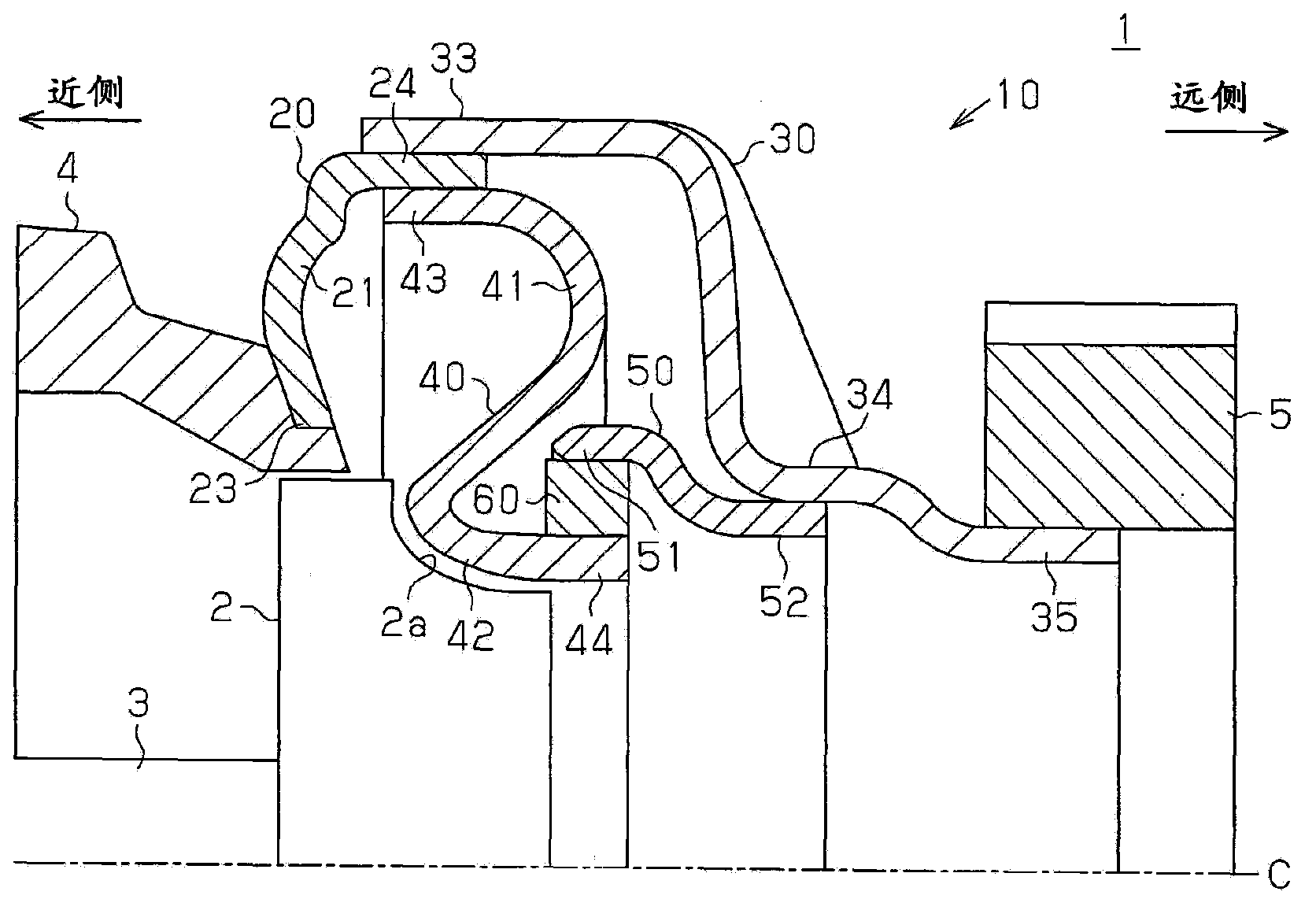
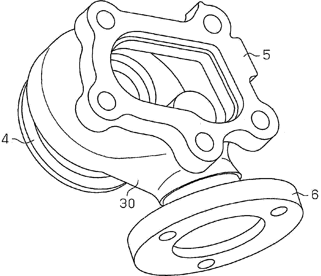
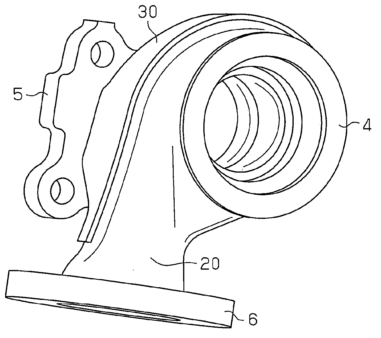
[0040] figure 1 A partial cross-sectional structure of the exhaust turbocharger 1 in this embodiment is shown. figure 2 The three-dimensional structure of the turbine housing 10 viewed from the side corresponding to the distal flange 5 is shown. image 3 The three-dimensional structure of the turbine housing 10 viewed from the side corresponding to the proximal flange 4 is shown.

[0041] In the following description, the side close to the turbine shaft 3 along the axial direction C of the turbine wheel 2 ( figure 1 The left side in ) is called the proximal side, while the side that will be away from the turbine axis 3 ( figure 1 The right side) is called the far side.

[0042] Such as Figure 1 to Figure 3 As shown in , the exhaust turbocharger 1 includes a turbine shaft 3, a turbine wheel 2 and a turbine housing...


PUM


Abstract

A turbine housing (10) comprises: an outer housing member and an inner housing member (40), wherein the outer housing member is provided with a base end-side housing section (20) and a front end-side housing section (30); the inner housing member (40) is disposed within the outer housing member and is provided with a shroud surface (42) facing a turbine wheel (2) in the axial direction (C). The front end section of the inner housing member (40) is a slide section (44) capable of sliding in the axial direction (C). The base end section (43) of the inner housing member (40) is affixed to the base end-side housing section (20) at a position further toward the front end side than the base end section (23) of the base end-side housing section (20). A scroll section is formed by the inner housing member (40) and the base end-side scroll section (21) of the base end-side housing section (20) and the base end-side scroll section (21) is located further toward the base end side than the inner housing member (40).

Description

technical field [0001] The invention relates to an exhaust-gas turbocharger for supercharging by means of a turbine wheel which can be rotated by the exhaust gas, and to a turbine housing which is the exhaust-gas turbocharger housing and encloses the turbine wheel. Background technique [0002] Generally, for example, Patent Document 1 discloses such a turbine housing and an exhaust turbocharger. [0003] As in Patent Document 1 figure 1 As shown in , the turbine casing disclosed in Patent Document 1 includes a pump wheel casing member (5), a discharge pipe (10) and an outer casing member (2), and the pump wheel casing member (5) surrounds the turbine pump wheel ( 9), the discharge pipe (10) is connected to the downstream part of the pump wheel casing member (5), and the outer casing member (2) surrounds the pump wheel casing member (5) and the discharge pipe (10). That is, the distal portion of the pump housing member (5) (Patent Document 1 figure 1 The left end part of...

Claims


Application Information

Patent Timeline
Patent Type & Authority Applications(China)
IPC IPC(8): F02B39/00
CPCF01D9/026F02C6/12F05D2220/40F05D2230/54F04D29/40
Inventor 前田治永井幸司矶谷知之松井裕树佐伯昌纪
Owner TOYOTA JIDOSHA KK
Why Eureka
Try Eureka